PLL_ChargePumpPLL : A charge-pump phase-locked loop (PLL)
A phase-locked loop (PLL) is a feedback system that generates an output clock of which phase is aligned with that of the input clock. In particular, a charge-pump phase-locked loop (CP-PLL) is a PLL that uses a charge-pump-based loop filter, which has a pole located at DC and can achieve a zero static phase error regardless of the input frequency.
This CP-PLL model is composed of a linear phase-frequency detector (PFD), a charge-pump loop filter, a voltage-controlled oscillator (VCO), and a frequency divider. The PFD compares the phases of the input clock in and feedback clock fb and expresses their error using the pulsewidth difference of the up and dn outputs. The charge-pump loop filter then adjusts the control voltage vc in response to this error. And the VCO generates a set of multiphase clocks out of which frequency and phase are controlled by vc. When a frequency divider with a dividing ratio of N is present in the feedback path, the PLL generates an N-times higher-frequency output clocks out than the input clock in.
Input/Output Terminals
| Name | I/O | Type | Description |
| out[7:0] | output | xbit | output clocks |
| in | input | xbit | input clock |
Parameters
| Name | Type | Default | Description |
| Iup | real | 100e-6 | charge-pump up current |
| Idn | real | 100e-6 | charge-pump down current |
| Vinit | real | 0.5 | initial control voltage |
| Rs | real | 20e3 | loop-filter series resistance |
| Cs | real | 0.79e-12 | loop-filter series capacitance |
| Cp | real | 79e-15 | loop-filter shunt capacitance |
List of Children Cells
| BLK_ChargePumpLoopFilter : A loop filter for charge-pump PLL |
| DIV_ProgDividerSyncRetimer : A programmable frequency divider with a synchronous retimer |
| OSC_LinearVCO8O : A voltage-controlled oscillator (VCO) with a linear V-to-f characteristic and 8 outputs |
| PDC_LinearPFD : A linear phase-frequency detector (PFD) |
List of Testbenches
| tb_check_lock : A testbench for checking the locking behavior of a PLL |
| tb_meas_freqstep : A testbench for measuring the frequency step response of a PLL |
| tb_meas_jhist : A testbench for measuring the jitter histogram of a PLL output clock |
| tb_meas_jtran : A testbench for measuring the jitter transfer characteristics of a PLL |
| tb_meas_phasestep : A testbench for measuring the phase step response of a PLL |
| tb_meas_phnoise_cpmismatch : A testbench for measuring the reference spurs of a PLL due to charge pump current mismatch |
tb_check_lock : A testbench for checking the locking behavior of a PLL
This testbench checks if a phase-locked loop (PLL) can successfully acquire a lock by simulating its locking transient. The testbench applies a fixed-frequency reference clock to the PLL, of which initial frequency starts from a value far from the desired lock position. The frequency and phase trajectories of the PLL output clock indicate whether the PLL has the capability of acquiring the correct lock when it is started from the said initial condition.
`include "xmodel.h"

module tb_check_lock();

    parameter real freq_ref = 2.0e9;    // reference clock frequency

    xbit clk_ref;                       // reference clock
    xbit [7:0] clk_out;                 // output clock
    xbit clk_out0;                      // alias for clk_out[0]

    // DUT phase-locked loop
    PLL_ChargePumpPLL  DUT (.in(clk_ref), .out(clk_out));

    // reference clock generator
    clk_gen #(.freq(freq_ref))  clk_gen(clk_ref);

    // probing
    initial begin
        $xmodel_dumpfile();
        $xmodel_dumpvars("level=", 2);
    end
    assign clk_out0 = clk_out[0];
    probe_freq  fq_out(clk_out0);
    probe_phase #(.freq(8*freq_ref)) ph_out(clk_out0);

endmodule
Simulation Results
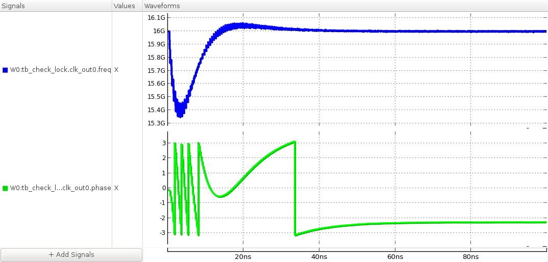
Figure. locking transients of the output clock’s frequency and phase.
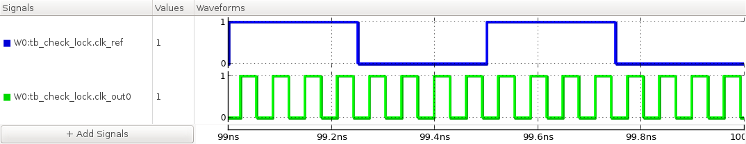
Figure. steady-state waveforms of the input and output clocks.
tb_meas_freqstep : A testbench for measuring the frequency step response of a PLL
This testbench measures the response of a PLL to a step change in its input clock frequency. Once the PLL acquires a lock, the testbench applies a step change in its input clock frequency using the step_gen and freq_to_clk primitives. The responses in the output clock frequency and phase indicate the loop bandwidth and stability of the PLL.
`include "xmodel.h"

module tb_meas_freqstep();

    parameter real freq_ref = 2.0e9;        // reference frequency
    parameter real freq_step = 200e6;       // frequency step amount
    parameter real step_delay = 100e-9;     // frequency step delay

    xreal   freq_in;                        // input frequency
    xbit    clk_ref;                        // reference clock
    xbit    [7:0] clk_out;                  // output clock
    xbit    clk_out0;                       // alias for clk_out0

    // DUT phase-locked loop
    PLL_ChargePumpPLL  DUT (.in(clk_ref), .out(clk_out));

    // frequency step generator
    step_gen    #(.init_value(freq_ref), .change(freq_step), .delay(step_delay))
                freq_gen(freq_in);
    freq_to_clk clk_gen(.in(freq_in), .out(clk_ref));

    // probing
    initial begin
        $xmodel_dumpfile();
        $xmodel_dumpvars("level=", 2);
    end

    assign clk_out0 = clk_out[0];
    probe_freq  fq_out(clk_out0);
    probe_freq  fq_in(clk_ref);

endmodule
Simulation Results
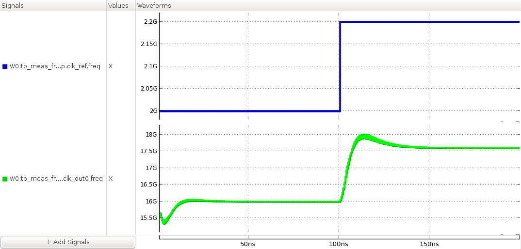
Figure. frequency step response of the PLL.
tb_meas_jhist : A testbench for measuring the jitter histogram of a PLL output clock
This testbench measures the jitter histogram and phase noise spectrum of the output clock of a phase-locked loop (PLL). The testbench first lets the PLL acquire a lock by applying a fixed-frequency clock input and waiting for the PLL responses to settle. Then it collects the output clock transitions and analyzes the jitter histogram and phase noise spectrum. The jitter histogram shows the probability density function of the clock edge position and the phase noise spectrum shows the frequency content of the jitter or phase noise. The jitter and phase noise of a PLL output clock can be contributed by the noise from the input clock and internal components.
`include "xmodel.h"

module tb_meas_jhist();

    parameter real freq_ref = 2.0e9;    // reference clock frequency
    parameter real RJ_rms = 10e-12;     // reference clock random jitter (RMS)
    parameter real t_lock = 200e-9;     // time required for PLL to lock

    xbit clk_ref;                       // reference clock
    xbit [7:0] clk_out;                 // output clock
    xbit clk_out0;                      // alias for clk_out0

    // DUT phase-locked loop
    PLL_ChargePumpPLL  DUT(.in(clk_ref), .out(clk_out));

    // reference clock generator
    clk_gen     #(.freq(freq_ref), .RJ_rms(RJ_rms))
                clk_gen(clk_ref);

    // probing
    assign clk_out0 = clk_out[0];
    probe_xbit  #(.start(t_lock)) probe_out(clk_out0);

endmodule
Simulation Results
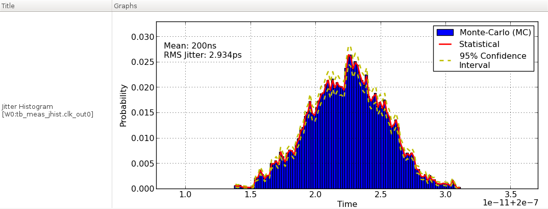
Figure. jitter histogram of PLL output clock.
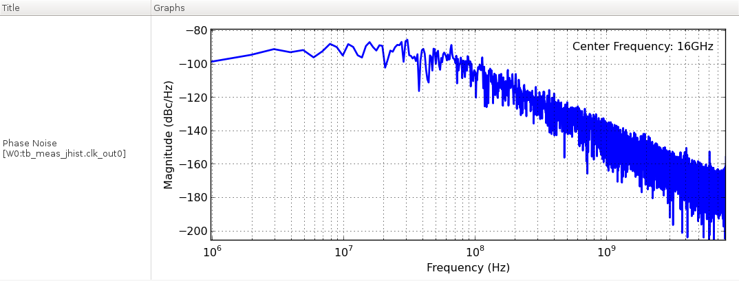
Figure. phase noise spectrum of PLL output clock.
tb_meas_jtran : A testbench for measuring the jitter transfer characteristics of a PLL
This testbench measures the jitter transfer characteristics of a phase-locked loop (PLL). The testbench measures the jitter transfer function at each frequency by applying a sinusoidal jitter to the input clock using a clk_gen primitive and measuring the magnitude and phase of the resulting sinusoidal response in the output clock phase. The jtran.py script repeats this measurement while sweeping the sinusoidal jitter frequency and constructs the overall jitter transfer function of the PLL.
`include "xmodel.h"

module tb_meas_jtran();

    parameter real ref_freq = @ref_freq;    // input clock frequency
    parameter real SJ_amp = @sj_amp;        // input sinusoidal jitter amplitude in UI
    parameter real SJ_freq = @sj_freq;      // input sinusoidal jitter frequency in Hz
    parameter real t_lock = @t_lock;        // initial simulation time (PLL locking time)

    xbit clk_ref;                           // reference clock
    xbit [7:0] clk_out;                     // output clock
    xbit clk_out0;                          // alias for clk_out[0]

    // charge-pump phase-locked loop
    PLL_ChargePumpPLL   #(.Iup(100e-6), .Idn(100e-6),
                  .Rs(20e3), .Cs(790e-15), .Cp(79e-15), .Vinit(0.4))
                cp_pll(.in(clk_ref),.out(clk_out));

    // reference clock generator with sinusoidal jitter
    clk_gen     #(.freq(ref_freq), .SJ_amp(SJ_amp), .SJ_freq(SJ_freq))
                clk_gen(clk_ref);

    // probing
    assign clk_out0 = clk_out[0];
    probe_phase #(.freq(ref_freq*8), .start(t_lock), .phase_wrap(0))
                probe_phase(clk_out0);

endmodule
Simulation Results
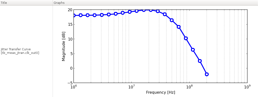
Figure. jitter transfer function of the PLL.
tb_meas_phasestep : A testbench for measuring the phase step response of a PLL
This testbench measures the response of a PLL to a step change in its input clock phase. Once the PLL acquires a lock, the testbench applies a step change in its input clock phase using the step_gen and phase_to_clk primitives. The responses in the output clock frequency and phase indicate the loop bandwidth and stability of the PLL.
`include "xmodel.h"

module tb_meas_phasestep();

    parameter real freq_ref = 2.0e9;        // reference frequency
    parameter real phase_step = 0.1*M_PI;   // phase step amount
    parameter real step_delay = 100e-9;     // phase step delay

    xreal phase_ref;                        // reference phase
    xbit clk_ref;                           // reference clock
    xbit [7:0] clk_out;                     // output clock
    xbit clk_out0;                          // alias for clk_out0

    // DUT phase-locked loop
    PLL_ChargePumpPLL      DUT(.in(clk_ref), .out(clk_out));

    // phase step generator
    step_gen        #(.init_value(0.0), .change(phase_step), .delay(step_delay))
                    phase_gen(phase_ref);
    phase_to_clk    #(.freq(freq_ref)) clk_gen(.in(phase_ref), .out(clk_ref));

    // probing
    initial begin
        $xmodel_dumpfile();
        $xmodel_dumpvars("level=", 2);
    end

    assign clk_out0 = clk_out[0];
    probe_freq      fq_out(clk_out0);
    probe_phase     #(.freq(freq_ref*8), .phase_wrap(0)) ph_out(clk_out0);
    probe_phase     #(.freq(freq_ref)) ph_ref(clk_ref);

endmodule
Simulation Results
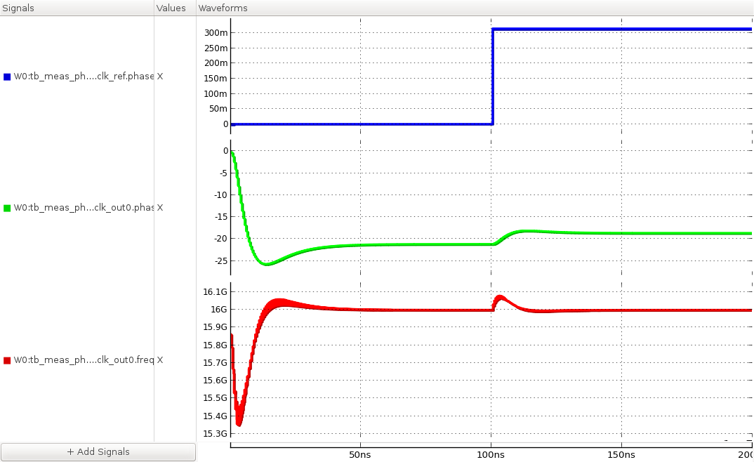
Figure. phase step response of the PLL.
tb_meas_phnoise_cpmismatch : A testbench for measuring the reference spurs of a PLL due to charge pump current mismatch
This testbench measures the phase noise spectrum of a phase-locked loop (PLL) when its charge pump has a mismatch between the up and down currents Iup and Idn. Such current mismatch may cause periodic disturbance on the control voltage, resulting in the periodic jitter in the output clock and the reference spurs in the phase noise spectrum. The testbench setup is identical to the testbench for measuring the jitter histogram, first letting the PLL acquire a lock to a fixed-frequency clock input and collecting the output clock transitions to analyze the phase noise spectrum. Reference spurs are spurious tones observed in the phase noise spectrum at frequency offsets equal to the integer multiples of the reference frequency.
`include "xmodel.h"

module tb_meas_phnoise_cpmismatch();

    parameter real freq_ref = 2.0e9;    // reference clock frequency
    parameter real t_lock = 200e-9;     // time required for PLL to lock

    xbit clk_ref;                       // reference clock
    xbit [7:0] clk_out;                 // output clock
    xbit clk_out0;                      // alias for clk_out0

    // DUT phase-locked loop
    PLL_ChargePumpPLL  #(.Iup(100e-6), .Idn(200e-6))
                DUT(.in(clk_ref), .out(clk_out));

    // reference clock generator
    clk_gen     #(.freq(freq_ref)) clk_gen(clk_ref);

    // probing
    initial begin
        $xmodel_dumpfile();
        $xmodel_dumpvars("level=", 1, DUT);
    end

    assign clk_out0 = clk_out[0];
    probe_xbit  #(.start(t_lock)) probe_out(clk_out0);
    probe_freq  fq_out(clk_out0);
    probe_phase #(.freq(8*freq_ref)) ph_out(clk_out0);

endmodule
Simulation Results
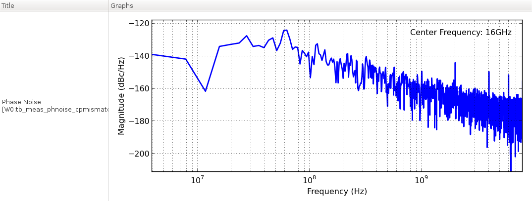
Figure. phase noise spectrum of the PLL output clock.