CDR_PhaseInterpCDR : A phase-interpolator based clock-and-data recovery unit (CDR)
A clock-and-data recovery unit (CDR) is a key component in high-speed wireline receivers that recovers an optimal clock to sample and detect an incoming data stream. In particular, a phase-interpolator based CDR is a feedback system that adjusts the phase of the recovered clock using a phase interpolator based on the timing error information provided by the phase detector.
This phase-interpolator based CDR model has a basic architecture described by S. Sidiropoulos, et al in 1997. The CDR consists of two feedback loops, a primary loop and a secondary loop, where the primary loop is a charge pump phase-locked loop (PLL) generating a set of multiphase clocks mclk spanning 360-degrees from a reference clock clk_ref, and the secondary loop is a phase-interpolator based delay-locked loop (DLL) selecting two adjacent clock phases and interpolating between them to realize a delay line with an effectively infinite range.
Ref: S. Sidiropoulos, et al., “A Semi-Digital Dual Delay-Locked Loop”, IEEE Journal of Solid-State Circuits, Nov. 1997.
This architecture has widespread popularity due to its clean partition between the digital and analog components, namely the phase-locked loop, phase-interpolator, bang-bang phase detector, and digital controller.
Input/Output Terminals
| Name | I/O | Type | Description |
| clk | output | xbit | output clock |
| data | output | xbit | output data |
| clk_ref | input | xbit | reference clock |
| in_neg | input | xreal | input data (neg) |
| in_pos | input | xreal | input data (pos) |
List of Children Cells
| CDR_PhaseInterpCDR_LoopFilter : A digital loop filter for a phase-interpolating CDR |
| DPC_PhaseDAC : A phase interpolator for phase-domain digital-to-analog converter (DAC) |
| PDD_AlexanderPD : An Alexander-type bang-bang phase detector (PD) for NRZ data input |
| PLL_ChargePumpPLL : A charge-pump phase-locked loop (PLL) |
List of Testbenches
| tb_check_lock : A testbench for checking the locking behavior of a CDR |
| tb_meas_bathtub : A testbench for measuring the BER bathtub curve of a CDR |
| tb_meas_jhist : A testbench for measuring the jitter histogram of a CDR recovered clock |
| tb_meas_jtol : A testbench for measuring the jitter tolerance of a CDR |
| tb_meas_jtran : A testbench for measuring the jitter transfer function of a CDR |
tb_check_lock : A testbench for checking the locking behavior of a CDR
This testbench checks if a clock-and-data recovery unit (CDR) can successfully acquire a lock by simulating its locking transient. Particularly for this phase-interpolating CDR under test, the testbench supplies a PRBS data stream to the CDR and a reference clock of which frequency is coherent with the data rate. The locking transients of the primary multi-phase generation PLL and the secondary phase-interpolator based delay-locked loop indicate whether the CDR has the capability of acquiring the correct phase lock.
`include "xmodel.h"

module tb_check_lock();

    parameter real tx_freq = 16.0e9;     // transmitter clock frequency
    parameter real ref_freq = 2.0e9;     // local reference clock frequency

    // variables
    xbit    prbs;                        // input prbs stream
    xbit    prbs_inv;                    // inverted input prbs stream
    xbit    tx_clk;                      // transmitter clock
    xreal   tx_out_pos;                  // transmitter output (pos)
    xreal   tx_out_neg;                  // transmitter output (neg)
    xbit    ref_clk;                     // reference clock for cp_pll
    xbit    rx_clk;                      // recovered clock
    xbit    data;                        // recovered data

    // transmitter
    prbs_gen    prbs_gen(.trig(tx_clk), .out(prbs));
    inv_xbit    inv(.in(prbs), .out(prbs_inv));
    clk_gen     #(.freq(tx_freq))   clk_tx(tx_clk);
    clk_gen     #(.freq(ref_freq))  clk_ref(ref_clk);
    transition  #(.rise_time(5e-12), .fall_time(5e-12),
                  .value0(0), .value1(0.1))
                tx_driver_pos(.in(prbs), .out(tx_out_pos));
    transition  #(.rise_time(5e-12), .fall_time(5e-12),
                  .value0(0), .value1(0.1))
                tx_driver_neg(.in(prbs_inv), .out(tx_out_neg));

    // PI-CDR
    CDR_PhaseInterpCDR  DUT (.in_pos(tx_out_pos), .in_neg(tx_out_neg),
                     .clk_ref(ref_clk), .clk(rx_clk), .data(data));

    // probing
    probe_xbit  probe_prbs(prbs);
    probe_xreal probe_txout_pos(tx_out_pos);
    probe_xreal probe_txout_neg(tx_out_neg);
    probe_xbit  probe_data(data);
    probe_xbit  probe_rx_clk(rx_clk);

    probe_freq  probe_freq(rx_clk);
    probe_phase #(.freq(tx_freq), .phase_wrap(0))  probe_phase(rx_clk);

endmodule
Simulation Results
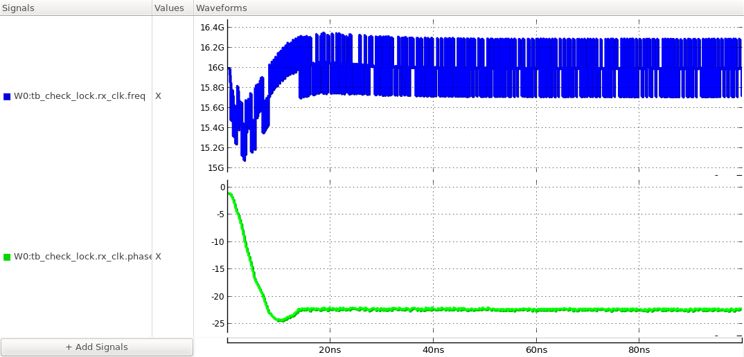
Figure. locking transients of the output clock’s frequency and phase.
tb_meas_bathtub : A testbench for measuring the BER bathtub curve of a CDR
This testbench measures the BER bathtub curve of a CDR by measuring the bit-error rate (BER) of the data sampled with a timing offset from the recovered clock timing. In other words, the output of an extra data sampler triggered by a delayed version of the recovered clock is compared to the output of the main data sampler triggered by the recovered clock to measure the BER and the BER bathtub curve is constructed by plotting the measured BERs versus timing offsets. The statistical simulation capability of XMODEL makes the measurement of BERs as low as 10^-20 possible with ~10,000 samples. From the BER bathtub curve, the maximum timing offset that can be tolerated to achieve a target BER (e.g. 10^-12) can be determined, indicating the timing margin of the CDR.
`include "xmodel.h"

module tb_meas_bathtub();

    parameter real tx_freq = 16.0e9;        // transmitter clock frequency
    parameter real ref_freq = 2.0e9;        // local reference clock frequency
    parameter real RJ_tx_rms = 1.0e-12;     // transmitter clock RMS random jitter
    parameter real RJ_ref_rms = 1.0e-12;    // local reference clock RMS random jitter
    parameter real t_offset = @t_offset;    // sampling offset of clock and data recovery
    parameter real t_lock = @t_lock;        // CDR initial lock time

    // variables
    xbit    prbs;                           // input prbs stream
    xbit    prbs_inv;                       // inverted input prbs stream
    xbit    tx_clk;                         // transmitter clock
    xreal   tx_out_pos;                     // transmitter output (pos)
    xreal   tx_out_neg;                     // transmitter output (neg)
    xbit    ref_clk;                        // reference clock for cp_pll
    xbit    rx_clk;                         // recovered clock
    xbit    data;                           // recovered data

    // transmitter
    prbs_gen     prbs_gen(.trig(tx_clk), .out(prbs));
    inv_xbit     inv(.in(prbs), .out(prbs_inv));
    clk_gen      #(.freq(tx_freq), .RJ_rms(RJ_tx_rms))
                 clk_tx(tx_clk);
    clk_gen      #(.freq(ref_freq), .RJ_rms(RJ_ref_rms))  clk_ref(ref_clk);
    transition   #(.rise_time(5e-12), .fall_time(5e-12),
                   .value0(0), .value1(0.1))
                 tx_driver_pos(.in(prbs), .out(tx_out_pos));
    transition   #(.rise_time(5e-12), .fall_time(5e-12),
                   .value0(0), .value1(0.1))
                 tx_driver_neg(.in(prbs_inv), .out(tx_out_neg));

    // PI-CDR
    CDR_PhaseInterpCDR    DUT (.in_pos(tx_out_pos), .in_neg(tx_out_neg),
                          .clk_ref(ref_clk), .clk(rx_clk), .data(data));

    // pd with sampling offset
    bit  up, dn;                            // PD output
    xbit rxclk_w_offset;                    // receiver clock with sampling offset
    xbit data_ref;                          // recovered data with sampling offset

    delay_xbit   #(.delay(t_offset))
                 delay_rxclk(.in(rx_clk), .out(rxclk_w_offset));

    PDD_AlexanderPD pd_alexander(.in_pos(tx_out_pos), .in_neg(tx_out_neg),
                                .clk(rxclk_w_offset), .dn(dn), .up(up), .data(data_ref));

    // probe bit error rate
    probe_ber    #(.start(t_lock))
                 probe_ber(.in_ref(data_ref), .in(data), .clk(rx_clk));

endmodule
Simulation Results
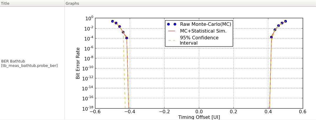
Figure. BER bathtub curve of the CDR.
tb_meas_jhist : A testbench for measuring the jitter histogram of a CDR recovered clock
This testbench measures the jitter histogram of a clock recovered by a clock-and-data recovery unit (CDR). The testbench first waits for the CDR to acquire a lock and then collects the timings of the recovered clock transitions to analyze its jitter histogram. The jitter histrogram shows the probability density function of the CDR clock jitter, which may be influenced by the timing/voltage noise in the input data as well as the noise in the CDR’s internal components.
`include "xmodel.h"

module tb_meas_jhist();

    parameter real tx_freq = 16.0e9;        // transmitter clock frequency
    parameter real ref_freq = 2.0e9;        // local reference clock frequency
    parameter real RJ_tx_rms = 1.0e-12;     // transmitter clock RMS random jitter
    parameter real RJ_ref_rms = 1.0e-12;    // local reference clock RMS random jitter
    parameter real t_lock = 200e-9;         // CDR locking time

    // variables
    xbit    prbs;                           // input prbs stream
    xbit    prbs_inv;                       // inverted input prbs stream
    xbit    tx_clk;                         // transmitter clock
    xreal   tx_out_pos;                     // transmitter output (pos)
    xreal   tx_out_neg;                     // transmitter output (neg)
    xbit    ref_clk;                        // reference clock for cp_pll
    xbit    rx_clk;                         // recovered clock
    xbit    data;                           // recovered data

    // transmitter
    prbs_gen    prbs_gen(.trig(tx_clk), .out(prbs));
    inv_xbit    inv(.in(prbs), .out(prbs_inv));
    clk_gen     #(.freq(tx_freq), .RJ_rms(RJ_tx_rms)) clk_tx(tx_clk);
    clk_gen     #(.freq(ref_freq), .RJ_rms(RJ_ref_rms)) clk_ref(ref_clk);
    transition  #(.rise_time(5e-12), .fall_time(5e-12),
                  .value0(0), .value1(0.1))
                tx_driver_pos(.in(prbs), .out(tx_out_pos));
    transition  #(.rise_time(5e-12), .fall_time(5e-12),
                  .value0(0), .value1(0.1))
                tx_driver_neg(.in(prbs_inv), .out(tx_out_neg));

    // PI-CDR
    CDR_PhaseInterpCDR  DUT (.in_pos(tx_out_pos), .in_neg(tx_out_neg),
                     .clk_ref(ref_clk), .clk(rx_clk), .data(data));

    // probing
    probe_xbit  #(.start(t_lock)) probe_clk(rx_clk);
    probe_phase #(.freq(tx_freq), .phase_wrap(0)) probe_phase(rx_clk);

endmodule
Simulation Results
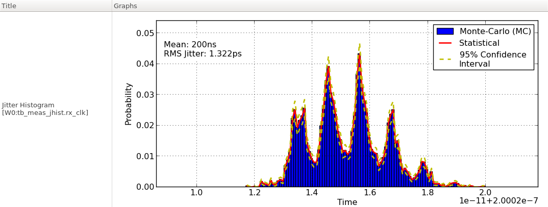
Figure. jitter histogram of the CDR output clock.
tb_meas_jtol : A testbench for measuring the jitter tolerance of a CDR
This testbench measures the jitter tolerance of a CDR by finding the maximum sinusoidal jitter (SJ) that can be tolerated by the CDR while meeting the target BER (e.g. 10^-12). For each SJ frequency, the jtol.py script performs an interactive search to determine the maximum SJ magnitude that can be tolerated. A typical jitter tolerance curve has two regions: a low-frequency region where the jitter tolerance improves as the SJ frequency decreases and a high-frequency region where the jitter tolerance stays relatively constant. The corner frequency between the low- and high-frequency regions indicates the tracking bandwidth of the CDR, while the jitter tolerance in the high-frequency region indicates the timing margin of the CDR.
`include "xmodel.h"

module tb_meas_jtol();

    parameter real tx_freq = 16.0e9;        // transmitter clock frequency
    parameter real ref_freq = 2.0e9;        // local reference clock frequency
    parameter real RJ_tx_rms = 1.0e-12;     // transmitter clock RMS random jitter
    parameter real RJ_ref_rms = 1.0e-12;    // local reference clock RMS random jitter

    parameter real SJ_amp = @sj_amp;        // transmitter clock sinusoidal jitter amplitude in UI
    parameter real SJ_freq = @sj_freq;      // transmitter clock sinusoidal jitter frequency in Hz
    parameter real t_lock = @t_lock;        // CDR initial lock time

    // variables
    xbit    prbs;                           // input prbs stream
    xbit    prbs_inv;                       // inverted input prbs stream
    xbit    tx_clk;                         // transmitter clock
    xreal   tx_out_pos;                     // transmitter output (pos)
    xreal   tx_out_neg;                     // transmitter output (neg)
    xbit    ref_clk;                        // reference clock for cp_pll
    xbit    rx_clk;                         // recovered clock
    xbit    data;                           // recovered data

    // transmitter
    prbs_gen    prbs_gen(.trig(tx_clk), .out(prbs));
    inv_xbit    inv(.in(prbs), .out(prbs_inv));
    clk_gen     #(.freq(tx_freq), .RJ_rms(RJ_tx_rms), .SJ_amp(SJ_amp), .SJ_freq(SJ_freq))
                clk_tx(tx_clk);
    clk_gen     #(.freq(ref_freq), .RJ_rms(RJ_ref_rms))  clk_ref(ref_clk);
    transition  #(.rise_time(5e-12), .fall_time(5e-12),
                  .value0(0), .value1(0.1))
                tx_driver_pos(.in(prbs), .out(tx_out_pos));
    transition  #(.rise_time(5e-12), .fall_time(5e-12),
                  .value0(0), .value1(0.1))
                tx_driver_neg(.in(prbs_inv), .out(tx_out_neg));

    // PI-CDR
    CDR_PhaseInterpCDR   DUT (.in_pos(tx_out_pos), .in_neg(tx_out_neg),
                         .clk_ref(ref_clk), .clk(rx_clk), .data(data));

    // probe bit error rate
    probe_ber   #(.start(t_lock))
                probe_ber(.in_ref(data), .in(data), .clk(rx_clk));
    probe_phase #(.freq(tx_freq),.start(t_lock),.phase_wrap(0))
                probe_phase(rx_clk);
    probe_phase #(.freq(tx_freq), .start(t_lock), .phase_wrap(0))
                probe_phase2(tx_clk);

endmodule
Simulation Results
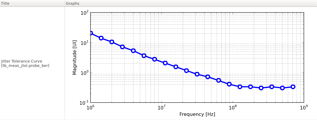
Figure. jitter tolerance of the CDR.
tb_meas_jtran : A testbench for measuring the jitter transfer function of a CDR
This testbench measures the jitter transfer characteristics of a clock-and-data recovery unit (CDR). The testbench measures the jitter transfer function at each frequency by applying a sinusoidal jitter to the input clock using a clk_gen primitive and measuring the magnitude and phase of the resulting sinusoidal response in the recovered clock phase. The jtran.py script repeats this measurement while sweeping the sinusoidal jitter frequency and constructs the overall jitter transfer function of the CDR.
`include "xmodel.h"

module tb_meas_jtran();

    parameter real tx_freq = 16.0e9;        // transmitter clock frequency
    parameter real ref_freq = 2.0e9;        // local reference clock frequency
    parameter real RJ_tx_rms = 1.0e-12;     // transmitter clock RMS random jitter
    parameter real RJ_ref_rms = 1.0e-12;    // local reference clock RMS random jitter

    parameter real SJ_amp = @sj_amp;        // transmitter clock sinusoidal jitter amplitude in UI
    parameter real SJ_freq = @sj_freq;      // transmitter clock sinusoidal jitter frequency in Hz
    parameter real t_lock = @t_lock;        // initial simulation time (CDR locking time)

    // variables
    xbit    prbs;                           // input prbs stream
    xbit    prbs_inv;                       // inverted input prbs stream
    xbit    tx_clk;                         // transmitter clock
    xreal   tx_out_pos;                     // transmitter output (pos)
    xreal   tx_out_neg;                     // transmitter output (neg)
    xbit    ref_clk;                        // reference clock for cp_pll
    xbit    rx_clk;                         // recovered clock
    xbit    data;                           // recovered data

    // transmitter
    prbs_gen    prbs_gen(.trig(tx_clk), .out(prbs));
    inv_xbit    inv(.in(prbs), .out(prbs_inv));
    clk_gen     #(.freq(tx_freq), .RJ_rms(RJ_tx_rms), .SJ_amp(SJ_amp), .SJ_freq(SJ_freq))
                clk_tx(tx_clk);
    clk_gen     #(.freq(ref_freq), .RJ_rms(RJ_ref_rms))  clk_ref(ref_clk);
    transition  #(.rise_time(5e-12), .fall_time(5e-12),
                  .value0(0), .value1(0.1))
                tx_driver_pos(.in(prbs), .out(tx_out_pos));
    transition  #(.rise_time(5e-12), .fall_time(5e-12),
                  .value0(0), .value1(0.1))
                tx_driver_neg(.in(prbs_inv), .out(tx_out_neg));

    // PI-CDR
    CDR_PhaseInterpCDR   DUT (.in_pos(tx_out_pos), .in_neg(tx_out_neg),
                         .clk_ref(ref_clk), .clk(rx_clk), .data(data));

    // probing
    probe_phase #(.freq(tx_freq), .start(t_lock), .phase_wrap(0))
                probe_phase(rx_clk);
    probe_freq  probe_freq(rx_clk);

endmodule
Simulation Results
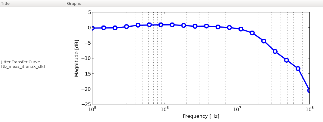
Figure. jitter transfer function of the CDR.