TDC_GatedOscTDC : A gated-oscillator-based time-to-digital converter (TDC)
A time-to-digital converter (TDC) measures the timing difference between two input signals clk_fb and clk_ref and produces the output out expressing the result in a digital format. A gated-oscillator-based TDC first measures the timing difference between the two input clocks using a linear phase-frequency detector (PFD) and then digitizes the pulsewidths of the PFD outputs by enabling an oscillator only when the PFD output is high and counting its frequency. By carrying over the residual quantization error accumulated as the oscillator’s phase, the TDC can also perform first-order noise-shaping, further improving the resolution.
Ref: M. Z. Straayer and M. H. Perrott, “A Multi-Path Gated Ring Oscillator TDC with First-Order Noise Shaping,” IEEE Journal of Solid-State Circuits, April 2009.
This gated-oscillator-based TDC model is composed of a linear PFD, gated oscillators, and digital counters. First, the linear PFD model measures the timing difference between the two input clocks clk_ref and clk_fb and produces the up and dn pulses with the corresponding pulsewidths. Second, a set of transition and freq_to_clk primitives generates a fixed-frequency clock clk_up or clk_dn, that is enabled only when the respective up or dn pulse is high. Finally, an inline primitive describes a set of two digital counters that count the frequency of clk_up and clk_dn and compute the net digitized output out.
Input/Output Terminals
| Name | I/O | Type | Description |
| out[3:0] | output | bit | output |
| clk_fb | input | xbit | feedback clock |
| clk_ref | input | xbit | reference clock |
Parameters
| Name | Type | Default | Description |
| out_min | int | -8 | minimum output range |
| delay_lsb | real | 64p | delay resolution |
List of Children Cells
| PDC_LinearPFD : A linear phase-frequency detector (PFD) |
List of Testbenches
| tb_meas_tfdc : A testbench for measuring the timing error vs. output transfer characteristics of a time-to-digital converter (TDC) |
tb_meas_tfdc : A testbench for measuring the timing error vs. output transfer characteristics of a time-to-digital converter (TDC)
This testbench measures the timing error vs. output transfer characteristics of a time-to-digital converter (TDC) by gradually changing the timing difference applied to the TDC’s two inputs. A probe_dc primitive sweeps the timing error and measures the TDC’s digital output assuming it is in two’s complement representation. The result shows the digital output code produced for each interval of the input timing difference.
Simulation Results
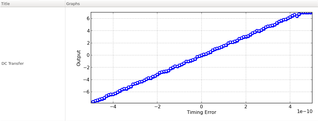
Figure. timing error vs. output transfer characteristics.