Using Advanced Features of GLISTER
Using xmodel Views
You can describe a cellview directly in SystemVerilog source code format using "xmodel" views. Similar to the verilog, systemVerilog, or veriloga views from Cadence®, xmodel views store the SystemVerilog sources, particularly the ones that use XMODEL data types such as xbit and xreal, XMODEL constants such as `one_xbit, `ground, and `INFINITY, and XMODEL primitives.
Creating a New xmodel View
You can create a new xmodel view using the same procedure with creating a new cellview. That is, select the File->New->Cellview pull-down menu from the CIW or the Library Manager window of Cadence® Virtuoso®. When the New File window pops up, select the library name and type in the cell name and view name that you want for the Library, Cell, and View fields of the dialog window, respectively. For the Type and Application fields, choose "xmodel" and "XMODEL IDE", respectively, as shown in Figure 21.
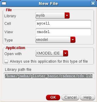
Figure 21. the New File dialog for the creation of a new xmodel view.
When a “Choose an XMODEL Source File” dialog box pops up (Figure 22), choose an existing XMODEL source file and click “Open”. Then, GLISTER will try to import the file into the specified cellview. If you’d like to start from an empty source, just click “Cancel”. Then, GLISTER will open a text-editor window filled with a model template (Figure 23).
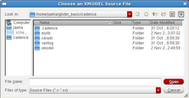
Figure 22. Choose an XMODEL Source File dialog box.
Although not mandatory, GLISTER encourages the users to write readable, well-documented codes by providing a template when a user starts with a new model file. This template is defined in $XMODEL_HOME/etc/xmodel.sv.template. The template starts with a header documentation defining the purpose and description of this module and defines the module with parameters and input/output ports. The parameters and input/output ports are listed in a way that the user can easily add comments for each of them. In fact, when the code is imported into the Cadence® design database, these comment lines will be imported as well and used as the descriptions for the corresponding items.
The source codes for the xmodel views may contain some special keywords such as %LIBNAME%, %CELLNAME%, and %VIEWNAME%, which will be replaced with the actual library, cell, and view names when they are exported (i.e. netlisted). These keywords help you avoid using fixed names in the source which may cause problems when the cellview is later copied or renamed into other cellviews with different names. For instance, by using %CELLNAME% as the module name, you do not have to edit the module name in the source to match the cell name every time you make a copy or rename the cellview.
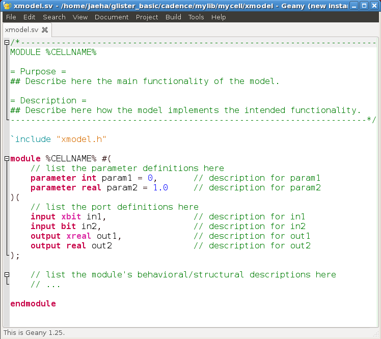
Figure 23. An example template source for xmodel views.
Once you enter all the source codes describing the module in SystemVerilog syntax, you can simply close the text editor window to finish entering. If you want to edit it again, just open the cellview either by double-clicking on the corresponding view name from the Library Manager window or select the File->Open menu from the CIW.
Importing an Existing XMODEL Source File as Cellview
You may already have an existing SystemVerilog source file that you want to import into the Cadence® design database, or you may prefer to use a different environment to create and edit the source files before importing them. In those cases, you can import the existing XMODEL source files or any SystemVerilog source files in general into the Cadence® design database by creating a new xmodel view and selecting the source file as explained in the previous subsection, or use the import menu from the CIW. This subsection will explain the latter.
First, select the File->Import->XMODEL pull-down menu from the CIW. Then an Import XMODEL Source dialog box will appear, asking for the destination library and the source file you want to import. Optionally, you may check the Create Symbol option, in which case, GLISTER will create a symbol having the input/output ports defined in the source file.
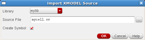
Figure 24. The Import XMODEL Source dialog window.
When you click the “OK” button, GLISTER will parse the source file and try to extract the information such as the module name, list of input/output ports, and list of parameters and their default values. GLISTER will then create an xmodel view for the cell that has the same name with the module name. If the source file contains multiple module definitions, only the first one will be used. Note that when you check the Create Symbol option, GLISTER may overwrite the existing symbol view of the corresponding cell.
If you need to import a large number of source files at once, consider writing a SKILL script that uses the xmodelImportCellView() SKILL API function explained in Section 6.2.
During the import process, GLISTER extracts some information such as the names and types of the ports and parameters from the source file, and stores them in the cellview as properties. And these properties will be automatically updated when you make changes to the xmodel view’s source file using the standard Cadence® Virtuoso® interface (e.g. opening the source file using the Library Manager or CIW). However, if you directly edit the source file using other means, you may need to explicitly tell GLISTER to parse the source files again and update the stored properties. For this purpose, please refer to the xmodelCheckCellView() and xmodelUpdateCellView() SKILL API functions explained in Section 6.2.
The current lists of supported data types for the ports and parameters that GLISTER can recognize during the import process are listed in Table 2.
Table 2. The lists of supported data types for the ports/parameters when GLISTER imports SystemVerilog models into xmodel views.
| Supported Data | Types for Ports/Parameters |
| Ports | xreal, real, xbit, bit, reg, wire, logic, int, integer |
| Parameters | bit, logic, real, integer, int, time, realtime, type, string |
Automatic Type Detection and Coercion
GLISTER is capable of performing automatic type detection and type coercion of signals during the netlisting process. Since the XMODEL’s key aim is an efficient simulation and verification of mixed-signal systems via SystemVerilog models, the models are likely to contain both analog and digital components that interface with different types of signals. For instance, analog parts may use signals in xreal or real types while digital parts may use signals in xbit or wire/reg types. Therefore, a schematic netlister for analog/mixed-signal system models must be able to produce SystemVerilog codes with multiple signal types. At the time of this writing, GLISTER is the only netlister with this capability. Most of the other model netlisters supporting Verilog-AMS or SystemVerilog 2012 connect all types of signals using wire‘s only, relying on the type coercion capability of the simulator itself. However, especially for SystemVerilog, type coercion is not supported by all major SystemVerilog simulators yet.
GLISTER Automatic Type Detection
Some cells or modules may have fixed signal types for their input/output ports. For example, the input/output ports of the "xmodel" views have the signal types defined in the SystemVerilog source files. To change the signal types, you need to modify the sources. Similarly, the XMODEL primitive cells contained in the xmodel_prims library have the pre-determined signal types for their input/output ports as described in the XMODEL Reference Manual.
On the other hand, some cells or modules may not have the input/output port signal types readily determined. One common example is a cell described as a schematic view as depicted in Figure 25. In Figure 25, a schematic view of cell A is enclosing an instance B1 of a cell B. As will be explained later, one can easily switch the view used for the instance B1 using the Cadence® Hierarchy Editor. For instance, you may want to use the xmodel view for one situation and use the verilog view in another. Each view may define the I/O ports in different signal types. For instance, the xmodel view may define them as xreal or xbit types, while the verilog view may define them as wire/reg types. Depending on which view is selected, you may want the signal types of the parent cellview’s ports (e.g. a1 and a2) to change to match the signal types of the instance ports (e.g. b1 and b2).
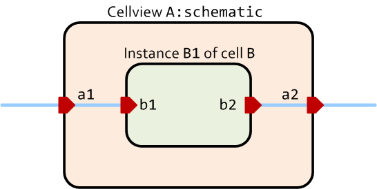
Figure 25. Illustration of automatic type detection in GLISTER.
GLISTER performs this automatic type detection when the I/O port signal types of a schematic cellview are defined as “auto“. In fact, all I/O pins or ports of a schematic cellview have the “auto” types by default.
You can check the signal type defined for a particular pin or port by selecting its pin symbol on the schematic and opening its Edit Object Properties window as shown in Figure 26. You can do this either by clicking the right mouse button and selecting Properties item from the pop-up menu or by pressing a short-cut key ‘Q’. If GLISTER is configured properly for your Cadence® Virtuoso® environment, then you will see some XMODEL-related CDF parameters. Among them, the XMODEL signal type defines the signal type of the corresponding pin. The same CDF parameters will also appear when you try to place a new pin on the schematic using the Add Pin dialog.
You have five choices for the signal type: auto, bit, xbit, real, and xreal. As explained, if you choose auto, GLISTER will try to determine the signal type automatically based on the selected views of the lower-level instances connected to this pin. On the other hand, if you choose any other signal types, then GLISTER will always use the specified signal type for the pin regardless of the views selected for the lower-level instances. Note that the bit type is equivalent to the wire or reg type in Verilog and logic type in SystemVerilog.
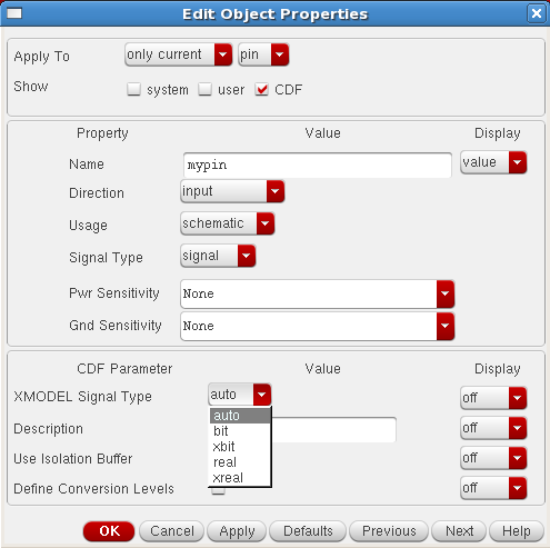
Figure 26. The Edit Object Properties dialog window for a pin.
As a side note, the Description CDF parameter allows you to add a short description on the pin. When generating the netlist, GLISTER adds this description as a comment next to the port definition, producing a well-documented model in SystemVerilog.
GLISTER Automatic Type Coercion
When GLISTER finds a mismatch between the signal types of this pin and the connected pins of the lower-level instances, GLISTER will resolve the difference by inserting a type-conversion connector. This is the automatic type coercion capability of GLISTER.
For instance, let’s assume that the view selected for the instance B1 in Figure 27 defines its input port b1 as real type and output port b2 as bit type. And further assume that the parent schematic view of the cell A defines its input port a1 as xreal and output port a2 as xbit. In this case, when GLISTER generates the netlists, it will automatically insert an xreal_to_real connector between the ports a1 and b1 and a bit_to_xbit connector between the ports b2 and a2. Please refer to the XMODEL Reference Manual for the full details on these connect primitives. The instances of these connect primitives will be netlisted as part of the cell A’s module description.
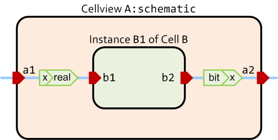
Figure 27. Illustration of automatic type coercion in GLISTER.
In some cases, an analog-type signal may be connected to a digital-type port or vice versa. For instance, the schematic view of the cell A in Figure 27 may define its input port a1 as xbit and output port a2 as xreal. In other words, an xbit-type port a1 is connected to a real-type port b1 and a bit-type port b2 is connected to an xreal-type port a2.
By default, a connection between an analog-type signal (e.g. xreal or real type) and a digital-type signal (e.g. xbit or bit type) is considered illegal and GLISTER will flag an error when you try to netlist such an A-D/D-A connection.
However, when the conversion level information is defined for the pins or globally, GLISTER considers that such an A-D/D-A connection is intended by the user and inserts a proper connect primitive when generating the netlist using the defined conversion levels.
There are multiple ways of defining the conversion levels. To define the conversion levels for a particular pin, you can use the CDF parameter entry of the Edit Object Properties or Add Pin dialog window of the pin (Figure 28). When you select the Define Conversion Levels checkbox, the additional fields will appear such as Level for Logic 1, Level for Logic 0, Threshold for Logic 1, Threshold for Logic 0, and Driving Strength.
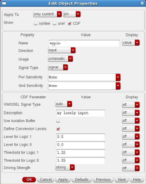
Figure 28. The Edit Object Properties window illustrating the definition of conversion levels.
The description of each parameter is listed in Table 3. Note that due to the current limitations of the connect primitives, the thresholds for logic 1 and logic 0 must be equal. For instance, a xreal_to_xbit primitive does not produce an 'X' value even when the logic-1 threshold is higher than the logic-0 threshold and the signal level resides between the two threshold levels. The conversion level information defined for a pin propagates towards the upper hierarchy levels. In other words, the auto-type pins not only propagate the signal type information of the lower-level instances, but also propagate the conversion level information.
If two connected ports have different conversion levels, GLISTER chooses the proper one depending on the type of A-D/D-A connection. For instance, if a digital output is driving an analog input, the levels for logic 1 and 0 information defined for the driving port is used. On the other hand, if an analog output is driving a digital input, the threshold levels defined for the receiving port is used.
Table 3. The pin CDF parameters defining XMODEL conversion levels.
| Parameter | Description |
| Level for Logic 1 | For D-to-A conversion, logic 1 is converted to this level. |
| Level for Logic 0 | For D-to-A conversion, logic 0 is converted to this level. |
| Threshold for Logic 1 | For A-to-D conversion, logic 1 is produced when the signal level is higher than this threshold. |
| Threshold for Logic 0 | For A-to-D conversion, logic 0 is produced when the signal level is lower than this threshold. |
| Driving Strength | Driving strength for wire/reg type outputs (possible choices: weak, pull, strong, and supply). |
You can also globally define the conversion levels for all pins. To do, you can define the following SKILL variables before the netlisting: xmodelConvLevel1, xmodelConvLevel0, xmodelConvThres1, xmodelConvThres0, and xmodelConvStrength. Each of them corresponds to the Level for Logic 1, Level for Logic 0, Threshold for Logic 1, Threshold for Logic 0, and Driving Strength parameters listed in Table 3, respectively. However, note that when you define the conversion levels globally, GLISTER considers all the A-D and D-A connections in the design as legal and will not flag any errors even for the erroneous ones.
xmodelConvLevel1 = 2.5
xmodelConvLevel0 = 0.0
xmodelConvThres1 = 1.25
xmodelConvThres0 = 1.25
xmodelConvStrength = "strong"
Sometimes, it may be necessary to define the conversion levels only for a particular connection between two instances. In other words, you may want to override the conversion levels defined for the connected pins or the ones defined globally just for a particular connection.
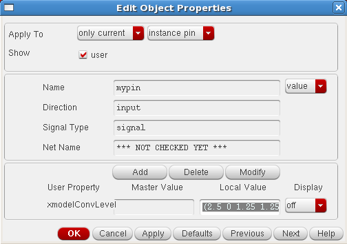
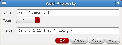
Figure 29. The Edit Object Properties and Add Property dialog windows for defining the xmodelConvLevel property of an instance pin.
You can define the conversion levels just for a particular instance connection by defining the xmodelConvLevel user property on the instance pins. Select the pin shape of the instance and open the Edit Object Properties dialog by clicking the right mouse button and selecting the Properties item from the pop-up menu, or by pressing a short-cut key 'Q'. When the dialog appears, select the user checkbox in the Show field and press the Add button on the bottom (Figure 29). Then, when an Add Pin dialog window appears, type xmodelConvLevel for the field Name, choose ILList for the field Type, and define the conversion levels in the field Value in the following list format:
( <level for 1> <level for 0> <threshold for 1> <threshold for 0> <driving strength> )
For instance:
( 2.5 0.0 1.25 1.25 "strong" )
Figure 29 demonstrates an example of defining this xmodelConvLevel user property.
Defining Model Parameters
Just as in typical Verilog modules, your model schematics can define parameters. Using model parameters has many advantages in building design database that is well-organized for reuse.
To define a new model parameter, select the GLISTER->Edit Model Parameters pull-down menu of the schematic editor. When the Edit Model Parameters dialog window like the one in Figure 30 appears, press the Add button to create a new parameter. From the Add/Modify Model Parameter dialog window that appears (Figure 31), you can define the name of the new parameter, its type (int, bit, real, or string), its default value, and its description.
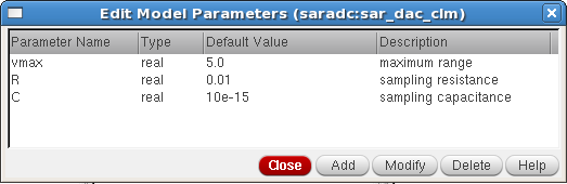
Figure 30. The Edit Model Parameters dialog window for defining model parameters.
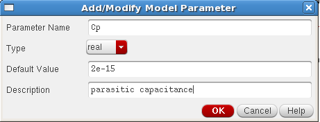
Figure 31. The Add/Modify Model Parameter dialog window for defining model parameters.
Once you define the model parameters for a schematic view, you can use them as part of the parameter value expressions of the instances. For instance, Figure 32 illustrates an example that uses a defined model parameter named "C" in the expression "32*C" that sets the capacitance of a capacitor primitive instance. Note that GLISTER does not use the Cadence CDF parameter expressions such as pPar, iPar, [@...], etc.
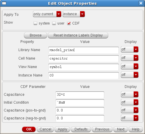
Figure 32. An example of using the model parameters in the instance parameter value expressions.
Figure 33 below shows an example SystemVerilog netlist generated from a schematic cellview which defines the model parameters (saradc:sar_dac_clm:schematic cellview from the glister_basic tutorial).
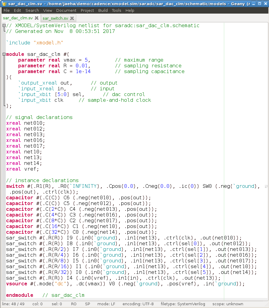
Figure 33. An example netlist produced from a schematic view with model parameters.
XMODEL Testbench Cellview
A simulation testbench feeds the stimuli to the device-under-test (DUT)’s inputs and observes its outputs (Figure 34). Almost every XMODEL simulation requires a testbench. This section describes how to setup a testbench for XMODEL simulations using GLISTER. In particular, GLISTER offers XMODEL Testbench Cellview and XMODEL Testbench Editor for configuring testbenches and defining various simulation options.
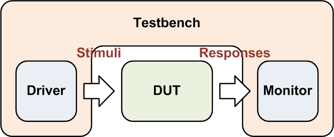
Figure 34. A simulation testbench.
There are two ways to make a testbench in GLISTER. One is to compose a testbench as a schematic cellview. The other is to compose one as a testbench cellview using the XMODEL Testbench Editor.
Composing Testbench as Schematic Cellview
You can compose a testbench by describing its components in a schematic form. As an example shown in Figure 35, you can create a basic testbench schematic by starting a new schematic, placing an instance of the DUT, adding stimuli primitives to drive the DUT’s inputs, and finally placing a dump primitive to record the simulated waveforms. As explained in Section 3.4 thru 3.6, from this schematic, you can generate the model netlists, run XMODEL simulations, and view simulated waveforms with interactive probing.
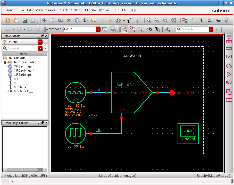
Figure 35. An example simulation testbench described as a schematic cellview (saradc:tb_sar_adc:schematic cellview in the glister_basic tutorial).
When recording multiple waveforms into a file, placing a dump primitive on a schematic cellview is a convenient alternative to using probe_* primitives. It has the same effect of using $xmodel_dumpfile() and $xmodel_dumpvars() system calls in the SystemVerilog sources. Please refer to the XMODEL User Guide for their usages and available options.
Users can define the similar options by editing the CDF parameters of the dump instance (see Figure 36). For instance, one can set the name of the file storing the waveforms, define its format (JEZ or FSDB format), define the start and stop times of the recording, and set the level of monitoring depth. If the depth level is set to 0, the dump primitive records all the signals included in the current cell and all of its lower-level cells. If the depth level is set to 1, it records only the signals in the current cell.
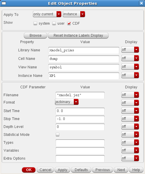
Figure 36. The CDF parameters available for a dump primitive.
The inline primitive can also be convenient when composing a testbench schematic. It allows you to add some SystemVerilog codes directly into the model netlist of a schematic cellview. It can be handy when you need to insert small amount of SystemVerilog codes to describe part of the testbench (e.g. initial statements).
To add SystemVerilog codes to a schematic cellview using inline primitives, first place its instance on the schematic and open its Edit Object Properties window. Then, press the “Open Inline Module Editor” button located in the CDF parameter section. Then an Edit Inline Module dialog window will appear. Please note that you must place the instance to the schematic first before opening the inline module editor. You cannot open the editor for an instance that has not been placed on the schematic yet.
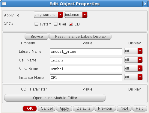
Figure 37. The Edit Object Properties dialog of an inline primitive.
Using the inline module editor shown in Figure 38, one can define the I/O ports of the inline module and describe the contents of the module in plain text. Note that this inline primitive is designed for inserting small amount of SystemVerilog codes without creating a new xmodel cellview. However, when the amount of SystemVerilog codes exceeds the level that can be easily described using the inline module editor, you should consider creating an xmodel view or using an XMODEL testbench cellview explained in the next subsection.
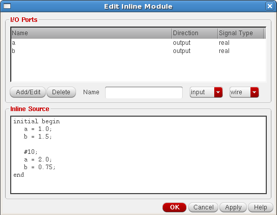
Figure 38. The inline module editor for an inline primitive.
While it might be the easiest, using a schematic cellview may not always be the most versatile way to compose a testbench. For instance, suppose that the DUT has many inputs. Placing a stimulus source and making a connection for each and every input of the DUT can be a tedious task. In this case, some advanced users may prefer using source codes, for instance, to utilize the advanced SystemVerilog language features to construct reusable, object-oriented testbenches. The next subsection describes how one can use the XMODEL testbench cellview and XMODEL testbench editor to compose a testbench with the wider range of options.
Composing Testbench as Testbench Cellview
The second way of composing a testbench is to create an XMODEL testbench cellview. An XMODEL testbench cellview is a new type of cellview introduced by GLISTER to store various information and files that describe a simulation testbench. In some sense, it has similar roles to the cellview storing the states of the Cadence® Analog Design Environment (ADE) simulation settings.
With XMODEL testbench cellviews, you can use a wider range of simulation options than with XMODEL testbench schematics. For instance, you can write your testbench in source texts, attach additional dependent files, specify hierarchy configurations, customize simulation commands, and even run XMODEL-SPICE co-simulations.
Perhaps it is a minor point, but another nice thing about using an XMODEL testbench cellview is that it can be one of the views of the cell under test. For instance, testbench cellviews named tb_locking, tb_freqstep, tb_phasestep can all reside under the same cell named pll along with its schematic view pll:schematic. And when these testbench cellviews are exported (i.e. netlisted), each testbench directory will be created under the directory named after the cell, 'pll'. It can be a better way of organizing the testbenches than having the separate testbench schematic views with different cell names such as tb_pll_locking:schematic, tb_pll_freqstep:schematic, and tb_pll_phasestep:schematic.
Just like other types of cellviews, you can create a new XMODEL testbench cellview from the Cadence® Library Manager or the CIW, but perhaps the more intuitive way is to create an XMODEL testbench cellview from the schematic cellview of the cell under test.
From the Virtuoso® Schematic Editor window displaying the cell schematic under test, select the GLISTER->Open Testbench Editor pull-down menu, or simply click the icon  from the toolbar menu (Figure 39). Then an XMODEL Testbench Editor window will appear (Figure 40).
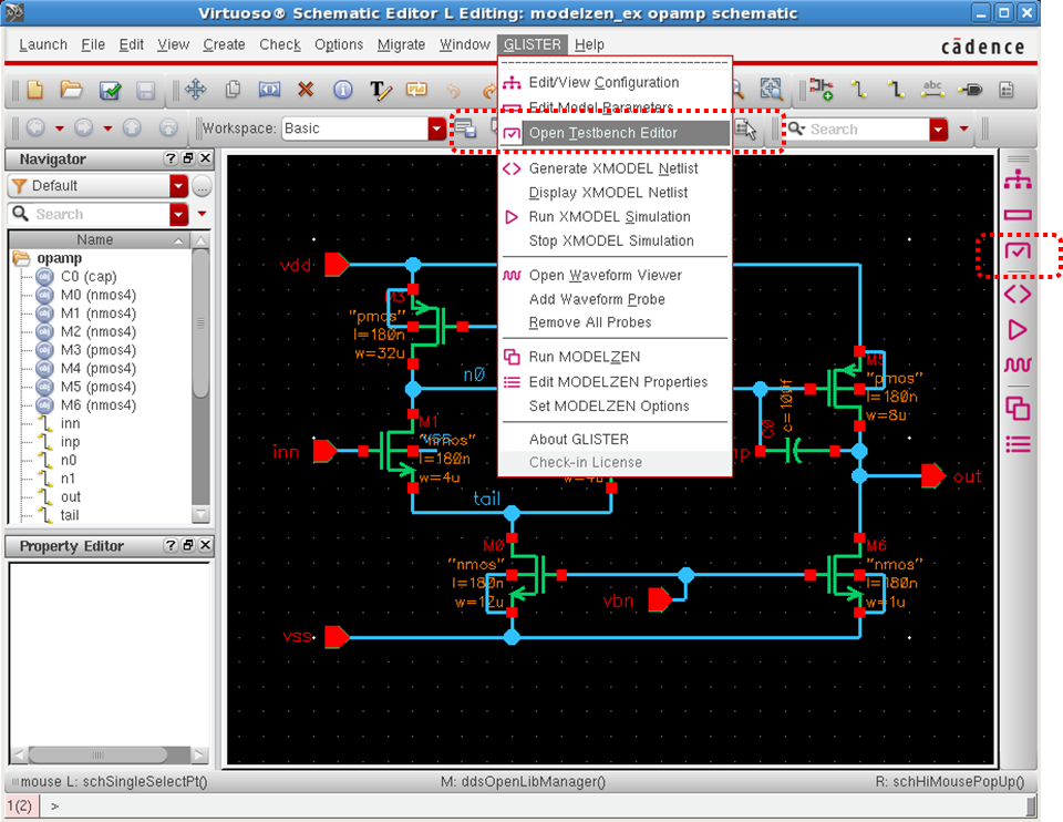
Figure 39. Opening the XMODEL Testbench Editor from the GLISTER pull-down menu.
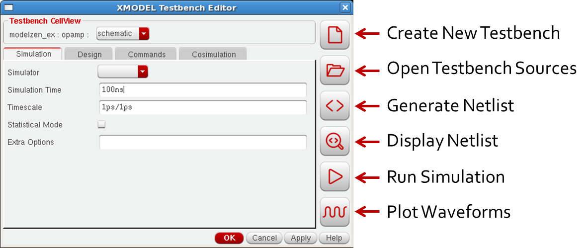
Figure 40. The XMODEL Testbench Editor window.
To create a new XMODEL testbench cellview, click on the Create New Testbench icon button  and enter the name of a new testbench view on the dialog box that pops up. To enforce consistent naming, the name of a new testbench view must start with a prefix
 "tb_". The name "tb" alone is also a valid name for a testbench view.
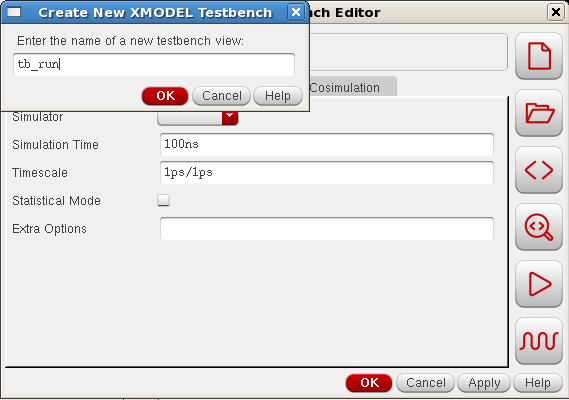
Figure 41. Creating a new XMODEL Testbench Cellview.
Once you create a new XMODEL testbench cellview, you can notice that you now have access to all the four tabs on the XMODEL Testbench Editor: Simulation, Design, Commands, and Cosimulation. In comparison, when you use a testbench schematic cellview, you can edit the content on the Simulation tab only, for choosing the SystemVerilog simulator, setting simulation time and time precision, etc. The following subsections will describe each of the tabs available.
Simulation Tab
On the Simulation tab, you can set the options related to running XMODEL simulations. For instance, the Simulator option chooses the SystemVerilog simulator you’d like to use for XMODEL simulation. Possible values are vcs, modelsim, or ncverilog. If you leave this option as blank, the default simulator defined by the $XMODEL_SIMULATOR environment variable will be used. Please refer to the XMODEL User Guide for more information on this environment variable.
The Simulation Time option specifies the duration of the simulation to run. The Timescale option specifies the simulation timescale and precision in Verilog format, such as 1ps/1ps. Only the values and format supported by the SystemVerilog simulator of your choice can be used.
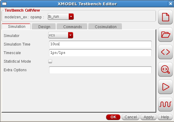
Figure 42. The Simulation tab of the XMODEL Testbench Editor.
The Statistical Mode option enables the statistical simulation of XMODEL. If it is enabled, XMODEL will calculate the statistical properties of the signals such as noise and jitter as part of the simulation. To view the results of statistical simulations, you should also turn on the statistical data recording option of the $xmodel_dumpvars system call or turn on the Statistical Mode option of the dump primitive placed on the schematic. For more details, please refer to the XMODEL User Guide.
The Extra Options field allows you to set any additional options you’d like to pass to the xmodel launcher. For instance, you can add --define <MACRO> options to define any macros. Also, you can define --elab-option or --sim-option options to define elaboration or simulation options specific to a particular SystemVerilog simulator, respectively. Please refer to the XMODEL User Guide for a full list of options available.
Design Tab
On the Design tab shown in Figure 43, you can specify one or more dependent cellviews or files to be included as part of the simulation.
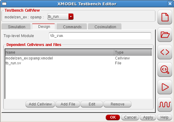
Figure 43. The Design tab of the XMODEL Testbench Editor.
When you add dependent cellviews to the list box, e.g., by clicking the Add Cellview button located on the bottom and choosing the cellview, GLISTER will netlist each of them to the /models subdirectory of the simulation directory when netlisting the testbench cellview. The cellviews that can be added include schematic views, xmodel views, and Verilog/SystemVerilog views as well as configuration views. Section 4.5 describes more details regarding the use of configuration views with GLISTER.
When you add dependent files, e.g. by clicking the Add File button and choosing the file, the files get copied into the testbench cellview. GLISTER exports these files to the simulation directory as-is when netlisting the testbench cellview. The files can be XMODEL or Verilog/SystemVerilog source files, or any other files that are required as part of the simulation. One example is a parameter file defining the parameter values for some XMODEL primitive instances. This basically provides a way of maintaining the dependent files as part of the Cadence® Virtuoso® design database.
You can double-click on the cellview or file item in the list box or press the Edit button after selecting the item to edit it. You can remove the item from the dependent cellviews and files by pressing the Remove button after selecting the item to remove.
The Top-level Module option defines a list of top-level modules for the SystemVerilog simulator to simulate. Typical SystemVerilog simulators simulate only the parts included in the hierarchies of these top-level modules. In most situations, the top-level module is the name of the top-level testbench module. You may list more than one top-level modules separated by white space.
When you create a new testbench cellview, by default GLISTER adds the schematic cellview found under the cell under test and creates an empty testbench source file defining a top-level testbench module, which is named after your testbench cellview name (e.g. tb_run). And GLISTER selects this testbench module as the top-level module by default. The new testbench source file is created from a template, of which location is defined by a SKILL variable xmodelTemplateTestbench. Its default value is:
xmodelTemplateTestbench = "$XMODEL_HOME/etc/tb_xmodel.sv.template"
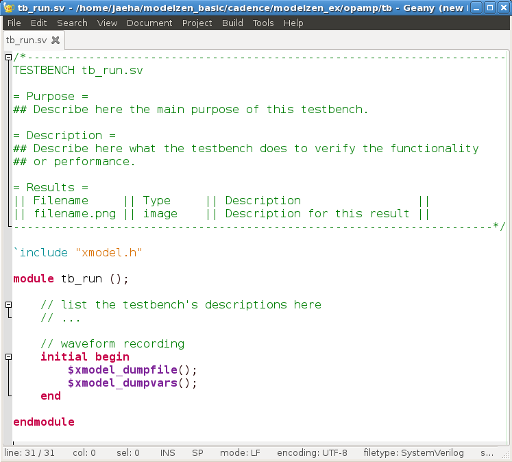
Figure 44. An example testbench source template used when creating a new XMODEL testbench cellview.
An example of this testbench source template is listed in Figure 44. Users may define their own templates and use them by overriding the xmodelTemplateTestbench SKILL variable after initializing the XMODEL/GLISTER setup for Cadence® Virtuoso® environment.
Commands Tab
On the Commands tab shown in Figure 45, you can customize the commands for running simulation and plotting waveforms.
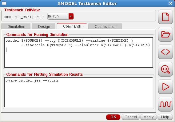
Figure 45. The Commands tab of the XMODEL Testbench Editor.
The commands define the actual lines used in the Makefile script, which is generated by GLISTER when netlisting the testbench cellview. Section 3.4 explains the basic organization of the simulation directory and an example content of the Makefile script generated by GLISTER. Specifically, the command lines defined for the Commands for Running Simulation and Commands for Ploting Simulation Results fields define the Makefile targets runsim and plotwave, respectively, and consequently the actions executed when the user presses the Run Simulation button ( ) and the Plot Waveforms button (
 ) on the XMODEL Testbench Editor, respectively. Therefore, users have full flexibility of defining these commands. For instance, users may want to launch a different waveform viewer program when viewing the simulated waveforms.
The variables used in the default commands such as $(SOURCES) and $(TOPMODULE) correspond to the option values defined in the Simulation and Design tabs. You may check their values defined in the Makefile script. Table 4 lists the available variables and their descriptions.
Table 4. A list of available variables for defining commands in the XMODEL Testbench Editor.
| Variables | Description |
$(SIMULATOR) |
SystemVerilog simulator (e.g. vcs, ncverilog, and modelsim). |
$(SIMTIME) |
Simulation time (e.g. 100ns). |
$(TIMESCALE) |
Simulation timescale and precision (e.g. 1ps/1ps). |
$(SIMOPTS) |
Extra simulation options. |
$(TOPMODULE) |
Top-level modules. |
$(SOURCES) |
A space-separated list of source files. |
$(DEPEND_FILES) |
A space-separated list of dependent files added in the Design tab. |
Cosimulation Tab
The Cosimulation tab shown in Figure 46 defines the options and control settings for running XMODEL-SPICE co-simulations. Typically, to run a simulation with the models partially described in digital HDLs such as Verilog/SystemVerilog and partially described in SPICE/Spectre netlists, you need to perform many preparations specific to your mixed-signal simulator. For instance, you may have to prepare a top-level input file for the SPICE simulator (because unlike Verilog, SPICE reads only one input file), create wrapper Verilog or Verilog-AMS modules for the SPICE cells, and prepare a control file listing which cells are defined in the SPICE netlist and which cells are defined in the Verilog files.
GLISTER performs all these preparation steps for you and lets you launch XMODEL-SPICE co-simulations directly using the XMODEL Testbench Editor. The Cosimulation tab is carefully crafted to fit multiple simulators from different vendors with a consistent interface. The more details on preparing the co-simulation netlists and running XMODEL-SPICE co-simulation using the XMODEL Testbench Editor are described in the Sections 4.5 and 4.6.
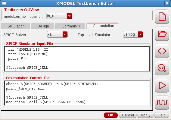
Figure 46. The Cosimulation tab of the XMODEL Testbench Editor.
XMODEL Testbench Editor Actions
By pressing the icon buttons located on the right side of the XMODEL Testbench Editor window (Figure 47), you can perform the following actions:
- Create a new testbench cellview

- Open and edit the sources added as dependent files

- Generate netlist for the testbench cellview

- Display the generated netlists

- Run simulation

- Plot waveforms

Most of these actions are self-explanatory. The Open Testbench Sources action ( ) offers a convenient way to open and edit all the source files added as dependent files to the testbench cellview. The Generate Netlist action (
 ) exports all the simulation settings to a
 Makefile script in the simulation directory and netlists all the dependent designs to the /models subdirectory. The Display Netlist action ( ) lets you examine the model netlists generated in the
 /models subdirectory.
The Run Simulation action ( ) and Plot Waveforms action (
 ) launch the simulator and waveform viewer, respectively. As explained in Section 3.4, when netlisting a testbench cellview, GLISTER prepares a stand-alone simulation directory that can also be executed on the Linux command-line using a
 Makefile script. In other words, pressing the Run Simulation button ( ) or Plot Waveforms button () is equivalent to executing the following commands on the Linux command line from the testbench cellview’s simulation directory, respectively:
make runsim
and
make plotwave

Figure 47. The XMODEL Testbench Editor window.
Using Configuration Views with GLISTER
A design cell stored in a Cadence® Virtuoso® design database may have more than one views that can be selected during netlisting. A configuration view (or config view in short) can define which view should be selected for the cell or for its particular instance in the design hierarchy.
When GLISTER performs netlisting of a design, it traverses the design hierarchy as specified by its configuration view. Therefore, you can control the way GLISTER netlists each cell or instance in the design hierarchy using the Cadence® Virtuoso® Hierarchy Editor. For general information on how to use the Cadence® Virtuoso® Hierarchy Editor to edit a configuration view, please consult the Cadence® documentation titled Virtuoso Hierarchy Editor User Guide.
Default Configuration View for GLISTER Netlisting
When GLISTER generates netlist for a schematic cellview, it looks for a configuration view defined for that cell. If there is only one configuration view, then GLISTER selects it and traverses down the design hierarchy as defined by that configuration view. If there are more than one configuration views for the cell, then GLISTER looks for the one with the name ‘config‘. If it exists, then GLISTER selects it. If not, GLISTER may choose any configuration view defined for the cell. You can check the selected configuration view by selecting the GLISTER->Edit/View Configuration pull-down menu from the schematic editor window. To force GLISTER to choose a particular configuration view, you can create an XMODEL testbench cellview and select the desired configuration view as the dependent cellview as explained in Section 4.4.
When the cell does not have any configuration views, GLISTER creates a temporary configuration view in memory with default settings and uses it for netlisting. This default configuration view has the following view list and stop list, of which values can be customized by overriding the values of the SKILL variables xmodelDefaultViewList and xmodelDefaultStopList, respectively:
- Default view list:
xmodel verilog functional behavioral hspiceD spectre veriloga sch_xmodel xmodel_sch schematic config - Default stop list:
xmodel verilog functional behavioral hspiceD spectre veriloga
xmodelDefaultViewList = list( "xmodel" "verilog" "functional" "behavioral"
                              "hspiceD" "spectre" "veriloga" "sch_xmodel"
                              "xmodel_sch" "schematic" "config" )
xmodelDefaultStopList = list( "xmodel" "verilog" "functional" "behavioral"
                              "hspiceD" "spectre" "veriloga" )
For your information, a view list defines a list of views that can be selected while traversing down the design hierarchy. In other words, GLISTER would not select a view of which name is not listed in this view list. On the other hand, a stop list defines a list of views that can stop the traversal. Typically, it lists leaf-type views that do not contain child instances. By default, the views that come first in the list have the higher priorities of being selected than the views that come later.
These default view and stop lists assume that the cells in your design hierarchy has the xmodel views named as xmodel and model schematic views named either as sch_xmodel, xmodel_sch, or just as schematic. If you want to select views with different names listed in the default view and stop lists during the GLISTER netlisting, you can modify the default view and stop lists assumed for the temporary configuration view by overriding the SKILL variables xmodelDefaultViewList and xmodelDefaultStopList.
If you want GLISTER to traverse the design hierarchy in a way that cannot be described by these simple rules using the view and stop lists, you should create a configuration view. You can create a new configuration view using the default view and stop lists by selecting the GLISTER->Edit/View Configuration pull-down menu, or clicking the  icon on the toolbar menu. Then GLISTER will prompt you for confirmation. You can also use the same menu for viewing or editing the existing configuration view that will be selected for netlisting the currently-editing schematic view.
Once a configuration view is created, you can use the Cadence® Virtuoso® Hierarchy Editor to override the default selected views for individual cells or instances in the design hierarchy. For instance, to override the selected view for a particular design cell, you can select its row in the Cell Bindings table on the Table View tab (Figure 48), click right mouse button on it, and select Set Cell View item from the pop-up menu to select a different view for the cell. To override the selected view for a particular instance in the design hierarchy, you can perform the similar actions on the instance found on the Tree View tab. Please refer to the Cadence® documentation titled Virtuoso Hierarchy Editor User Guide for the detailed instructions as well as other available features for editing the hierarchy.
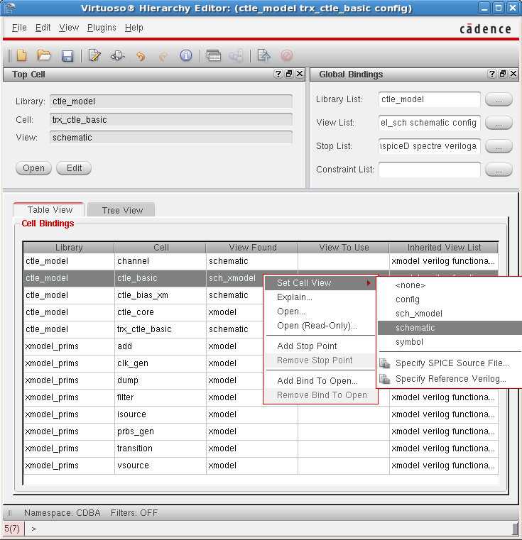
Figure 48. Cadence Virtuoso Hierarchy Editor window.
Using Configuration Views for Preparing Cosimulation Netlists
GLISTER can netlist a design of which hierarchy includes analog-type views, such as hspiceD, spectre, and veriloga. If such analog-type views exist in the design hierarchy, GLISTER assumes that you plan to run an XMODEL-SPICE co-simulation and prepares the netlists suitable for such co-simulation. In other words, GLISTER netlists the XMODEL or Verilog/SystemVerilog views in SystemVerilog format and netlists the analog-type views in its corresponding formats (e.g. SPICE, Spectre, or Verilog-A). GLISTER also creates the wrapper modules necessary for the analog-type cells that interface with the digital-type cells across the XMODEL-SPICE simulator boundary.
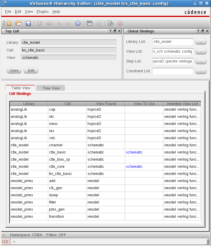
Figure 49. An example hierarchy configuration for generating XMODEL-SPICE co-simulation netlists (ctle_model:trx_ctle_basic:config example from the modelzen_basic tutorial).
You can edit the design hierarchy using the Cadence® Virtuoso® Hierarchy Editor to define which cells should be simulated in XMODEL/SystemVerilog and which cells should be simulated in SPICE. The usage is the same as explained in the previous subsection. Figure 49 shows an example hierarchy configuration from the modelzen_basic tutorial, which chooses schematic views containing hspiceD view instances for certain cells (e.g. ctle_basic). For more information on getting started with the modelzen_basic tutorial, please refer to the MODELZEN User’s Guide.
Due to the differences in the co-simulation netlist formats supported by different vendors, users must generate the co-simulation netlists using the XMODEL Testbench Editor, by defining an XMODEL testbench cellview that selects the simulator and proper configuration view as the dependent cellview. For instance, Cadence® NC-Verilog requires the analog cells be wrapped in Verilog-AMS modules having wreal type ports, while Synopsys VCS requires them be wrapped in SystemVerilog modules with real type ports. The XMODEL Testbench Editor also allows users to define additional options in the Cosimulation tab which may influence the netlists generated.
By default, GLISTER uses the Cadence® ADE netlister for generating netlists of the analog-type views. If you have customized the netlisting process for the analog-type views in your Cadence® Virtuoso® design environment, you can let GLISTER use the same customized process by overriding the default definition of a SKILL API function named xmodelGenNetlistSPICE. You can find more information about this SKILL API function in Section 7.7 of this documentation.
Running XMODEL-SPICE Co-simulation
One of the powerful features of GLISTER is that one can set-up and launch XMODEL-SPICE co-simulations using the XMODEL Testbench Editor. This section will explain this feature using the transceiver example (ctle_model:trx_ctle_basic:schematic) included in the modelzen_basic tutorial. Please refer to the MODELZEN User’s Guide for information how to get started with this tutorial. The example illustrates how to apply an XMODEL testbench to a design that contains some cells netlisted in SPICE or Spectre format.
The first step to setting up an XMODEL-SPICE co-simulation is to create an XMODEL testbench cellview. Then using the XMODEL Testbench Editor, choose the SystemVerilog simulator of your choice. GLISTER currently supports the co-simulation either with Cadence NC-Verilog (ncverilog or irun) or with Synopsys VCS.
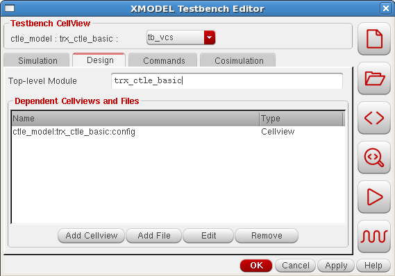
Figure 50. Adding a configuration view as dependent cellview to set up XMODEL-SPICE co-simulation.
The second step is to add a configuration view as a dependent cellview on the Design tab of the XMODEL Testbench Editor. This configuration view defines the views to be selected for the cells and instances included in the design hierarchy, as explained in the previous subsection. You may add additional testbench source files depending on whether your top-level testbench is a schematic view or a SystemVerilog source file. The trx_ctle_basic example in the tutorial uses a schematic view as the top-level testbench and hence does not require a source file be added as dependent file and uses the top-level cell name (trx_ctle_basic) as the top-level module (Figure 50).
The third step is to configure the options on the Cosimulation tab. Once you choose a SPICE solver to use with the SystemVerilog simulator, the default contents for the SPICE Simulation Input File and Cosimulation Control File fields will appear. Note that depending on whether you have chosen vcs or ncverilog as the simulator on the Simulation tab, the available SPICE solvers and default contents of these fields may vary. With vcs, the supported SPICE solvers include finesim, hsim, and xa. With ncverilog, the supported SPICE solvers include spectre, ultrasim, and aps. Figure 51 and Figure 52 illustrate the examples of setting up a vcs-xa co-simulation and ncverilog-spectre co-simulation for the trx_ctle_basic example, respectively.
The Top-level Simulator field defines whether you are using a Verilog-top configuration (verilog) or a SPICE-top configuration (spice). Currently, GLISTER supports only the Verilog-top configuration, meaning that the top-level cells must be Verilog/SystemVerilog modules and analog-type cells may not contain any Verilog module instances in their lower hierarchies. However, you can still perform XMODEL-SPICE co-simulation in SPICE-top configurations by manually preparing the netlists. It is just that GLISTER cannot prepare the co-simulation netlists when an analog-type view contains XMODEL/Verilog-type instances.
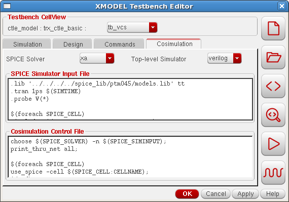
Figure 51. An example setup for vcs-xa co-simulation.
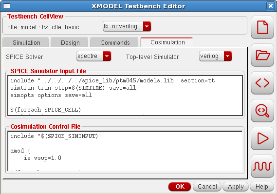
Figure 52. An example setup for ncverilog-spectre co-simulation.
Typically, to run an XMODEL-SPICE co-simulation, you need to prepare two files in addition to the model netlists: the SPICE simulator input file and co-simulation control file. GLISTER assists with the automatic generation of these files while offering full flexibility to the users.
SPICE Simulation Input File
The SPICE simulation input file is the input file to the SPICE simulator. Note that since most SPICE simulators take only one file as the input, this file has to include all individual SPICE/Spectre netlist files generated during the netlisting process. In addition, this input file must define the SPICE model libraries, operating conditions (e.g. temperature), transient analysis statements, and various options for setting accuracy and storing the results, etc.
The following boxes list the default content for the SPICE Simulation Input File field on the Cosimulation tab that appears for the cases of setting up the co-simulation with VCS and NC-Verilog, respectively. Users may freely edit the lines highlighted in red to define the SPICE model libraries, transient analysis statements, probe options, etc. Those lines are used as-is in the generated SPICE input file except that the $(SIMTIME) variable field is replaced with the simulation time defined on the Simulation tab (e.g. 100ns).
For VCS co-simulation:
.lib 'MODELS.LIB' TT
.tran 1ps $(SIMTIME)
.probe V(*)

$(foreach SPICE_CELL)
.include '$(SPICE_CELL:SPICE_NETLISTFILE)'
$(end)
For NC-Verilog co-simulation:
include "models.scs" section=tt
simtran tran stop=$(SIMTIME) save=all
simopts options save=all

$(foreach SPICE_CELL)
include "$(SPICE_CELL:SPICE_NETLISTFILE)"
$(end)
The rest of the lines that start with $(foreach SPICE_CELL) and end with $(end) direct GLISTER to insert a set of include statements to include all the SPICE/Spectre netlist files generated during the netlisting process. Note that the $(…) expressions used in those lines serve as placeholders rather than as executable commands and GLISTER may not support all possible combinations using these expressions. Please consult Scientific Analog if you find a need to modify this part.
Cosimulation Control File
The co-simulation control file defines the options specific to running Verilog-SPICE mixed-mode simulations. For instance, it may define the list of SPICE cells and Verilog cells and the way the signals between the cells should interface across the Verilog-SPICE boundary. Please refer to the proper documentations provided by the simulator vendor regarding the available options and syntaxes supported within this file. For co-simulation with VCS, this control file is typically called vcsAD.init and for co-simulation with NC-Verilog, the equivalent content is defined in the amsd section of the SPICE input file.
The following boxes list the default content for the Cosimulation Control File field on the Cosimulation tab that appears when setting up the co-simulation with VCS and NC-Verilog, respectively. For both cases, the content defines the connection rules and lists the cells to be simulated by the SPICE simulation solver. Again, the $(…) expressions define the placeholders where GLISTER will fill in when generating the control file. Users may edit the other parts (e.g. those highlighted in red) to define additional options for their mixed-mode simulations.
For VCS co-simulation:
choose $(SPICE_SOLVER) -n $(SPICE_SIMINPUT);
print_thru_net all;

$(foreach SPICE_CELL)
use_spice -cell $(SPICE_CELL:CELLNAME);
$(end)
For NC-Verilog co-simulation:
include "$(SPICE_SIMINPUT)"

amsd {
    ie vsup=1.0

$(foreach SPICE_CELL)
    portmap subckt=$(SPICE_CELL:CELLNAME) reffile="$(SPICE_CELL:VERILOG_NETLISTFILE)" autobus=yes porttype=name
    config cell=$(SPICE_CELL:CELLNAME) use=spice
$(end)
}
Once an XMODEL testbench cellview is properly set up with the above-mentioned information, the rest of the process, including generating netlists, running simulation, and view waveforms, are identical to the ones explained in Section 4.4. That is, you can perform these actions either using the icon buttons on the XMODEL Testbench Editor, or executing the exported Makefile script on the command-line. GLISTER offers a consistent user interface that extends well to the case of running XMODEL-SPICE cosimulation.
GLISTER License Management
Unlike XMODEL or MODELZEN which checks out the license when the simulation or model generation starts and checks in the license back when the execution is finished, GLISTER checks out the license when the user invokes a GLISTER action (e.g. netlisting) within the Cadence® Virtuoso® environment for the first time and continues to hold it for a certain inactivity period. This delayed release of the GLISTER license is to ensure the user’s uninterrupted access to the GLISTER features given the nature of interactive design entry tools.
Users can always release the GLISTER license at his or her will by selecting the GLISTER->Check-in License pull-down menu from the schematic editor window. If the GLISTER license has not been checked out, the menu item will be inactive. Users can also execute a SKILL function xmodelLicenseCheckIn() to release the license.
xmodelLicenseCheckIn()
As explained in Section 2.1, users can customize the license time-out period by defining the $XMODEL_LICENSE_TIMEOUT environment variable or the xmodelLicenseTimeOut SKILL variable. For more details, please refer to Section 2.1.