PDC_SRLatchPD : An edge-triggered phase-only detector with an set-reset (SR) latch
An edge-triggered phase-only detector (PD) measures the phase difference between two input clocks from the timings of their rising edges. This type of PD has an advantage that the measured outputs do not depend on the duty cycles of the input clocks.
This PD model consists of two pulse generators followed by an SR latch. Each of the pulse generators generates a short pulse whenever a rising edge of clk_ref or clk_fb arrives. When these pulses are fed to the SR latch, the SR latch produces the up and dn outputs bearing the pulse widths that indicate the phase difference between the two input clocks. The PD produces the equal pulsewidths for the up and dn outputs when the rising edges of the two input clocks are a half period apart (i.e. a phase difference of pi).
The model is composed of the XMODEL gate primitives to process the precise timing information of the input clocks without being limited by the simulation timestep of SystemVerilog.
Input/Output Terminals
| Name | I/O | Type | Description |
| dn | output | xbit | up output |
| up | output | xbit | down output |
| clk_fb | input | xbit | feedback clock |
| clk_ref | input | xbit | reference clock |
List of Testbenches
| tb_meas_tfdc : A testbench for measuring the transfer characteristic of a phase detector (PD) |
tb_meas_tfdc : A testbench for measuring the transfer characteristic of a phase detector (PD)
This testbench measures the transfer characteristics of a phase detector (PD), between the input phase difference and output pulse width difference. The testbench is configured using a probe_dc primitive, which gradually varies the phase of the reference clock clk_ref from -8 to 8 radians while keeping the phase of the reference clock clk_fb constant at 0.. For each input phase difference value being applied, the probe_dc primitive measures the difference in the pulse widths of the outputs up and dn as the net PD output.
The phase-only detector (PD) is expected to exhibit a transfer characteristic where the polarity of the output flips at the desired locking point and the magnitude increases as the input phase difference moves away from the locking point.
Simulation Results
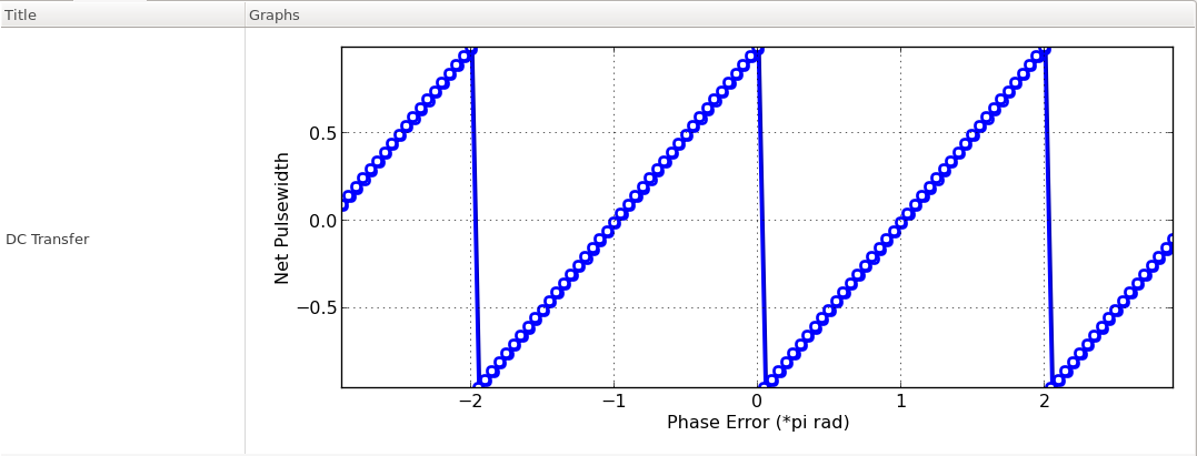
Figure. input-to-output transfer characteristics of the phase detector.