OSC_ExpDCO : A digitally-controlled oscillator (DCO) with an exponential D-to-f characteristic
A digitally-controlled oscillator (DCO) produces an output clock out of which frequency is controlled by a digital input in. In particular, this DCO model describes a DCO with an exponential digital-to-frequency (D-to-f) characteristic. In other words, the frequency of the output clock out changes exponentially with the input digital code in, as described by the following equation:
frequency = freq0 * (1+Rdco)^(in-in0)
The parameter freq0 sets the nominal frequency of the DCO when the input is at its nominal value set by the parameter in0. And the parameter Rdco defines the rate at which the frequency increases with the digital input. That is, the DCO frequency increases by a constant factor (1+Rdco) with respect to the present frequency whenever the input code increments by one LSB.
This DCO model is described using a Verilog code that computes the frequency value as an exponential function of the digital input code in and a freq_to_clk primitive that produces a clock with the corresponding frequency. The phase noise characteristics of the DCO can be modeled by defining the phase noise parameters of the freq_to_clk primitive, such as PN_fcenter, PN_foffset, PN_dbc, PN_fcorner, and PN_floor. For more information on these parameters, please refer to the documentation on the freq_to_clk primitive.
The DCO with an exponential D-to-f characteristic is useful when realizing a digital phase-locked loop (PLL) of which bandwidth scales with the operating frequency (i.e. a constant bandwidth/frequency ratio). This type of PLL, often referred to as a self-biased PLL or adaptive-bandwidth PLL, is one of the most effective ways to suppress the process, voltage, temperature (PVT) sensitivities of the PLL characteristics such as loop bandwidth and stability. For more information, please refer to:
J. Kim, et al, “Design of CMOS Adaptive-Bandwidth PLL/DLLs: A General Approach,” IEEE Trans. Circuits and Systems – I, Nov. 2003.
module OSC_ExpDCO #(
    parameter real in0 = 12'b100000000000, // nominal input value
    parameter real freq0 = 5.0e9,          // DCO frequency at nominal input value (Hz)
    parameter real Rdco = 0.004,           // DCO gain (%/step)
    parameter real PN_fcenter = -1.0,      // phase noise center frequency (Hz)
    parameter real PN_foffset = 0.0,       // phase noise offset frequency (Hz)
    parameter real PN_dbc = `INFINITY,     // phase noise measured in dBc/Hz (dBc/Hz)
    parameter real PN_fcorner = 0.0,       // 1/f^3 phase noise corner frequency (Hz)
    parameter real PN_floor = `INFINITY,   // phase noise floor measured in dBc/Hz (dBc/Hz)
    parameter real RJ_kappa = 0.0,         // RMS accumulated random jitter after 1 second (second)
    parameter real RJ_rms = 0.0            // RMS independent random jitter (second)
)(
    output xbit out,                       // output clock
    input  bit  [11:0] in                  // input control
);

    // variables
    real  freq;
    xreal freq_xr;

    // digital-to-frequency conversion (exponential)
    always @(in) begin
        freq = freq0 * `pow(1.0+Rdco/100.0, real'(in - in0));
    end
    real_to_xreal conn(.in(freq), .out(freq_xr));

    // frequency-to-clock conversion
    freq_to_clk   #(.num_phase(1), .PN_fcenter(PN_fcenter),
                    .PN_foffset(PN_foffset), .PN_dbc(PN_dbc),
                    .PN_fcorner(PN_fcorner), .PN_floor(PN_floor),
                    .RJ_kappa(RJ_kappa), .RJ_rms(RJ_rms))
                  freq2clk(.out(out), .in(freq_xr));

endmodule
Input/Output Terminals
| Name | I/O | Type | Description |
| out | output | xbit | output clock |
| in[11:0] | input | bit | input control |
Parameters
| Name | Type | Default | Description |
| in0 | real | 12’b100000000000 | nominal input value |
| freq0 | real | 5.0e9 | DCO frequency at nominal input value (Hz) |
| Rdco | real | 0.004 | DCO gain (%/step) |
| PN_fcenter | real | -1.0 | phase noise center frequency (Hz) |
| PN_foffset | real | 0.0 | phase noise offset frequency (Hz) |
| PN_dbc | real | `INFINITY | phase noise measured in dBc/Hz (dBc/Hz) |
| PN_fcorner | real | 0.0 | 1/f^3 phase noise corner frequency (Hz) |
| PN_floor | real | `INFINITY | phase noise floor measured in dBc/Hz (dBc/Hz) |
| RJ_kappa | real | 0.0 | RMS accumulated random jitter after 1 second (second) |
| RJ_rms | real | 0.0 | RMS independent random jitter (second) |
List of Testbenches
| tb_meas_tfdc : A testbench for measuring the digital-to-frequency characteristic of a DCO |
tb_meas_tfdc : A testbench for measuring the digital-to-frequency characteristic of a DCO
This testbench measures the digital-to-frequency (D-to-f) characteristic of a DCO by applying a gradually-varying digital input to the DCO and measuring its output frequency.
The measured frequency is expected to change with the digital input code according to the D-to-f equation assumed by the DCO model.
`include "xmodel.h"

module tb_meas_tfdc ();

    bit  [11:0] dcode;      // DCO digital code
    bit  [11:0] inc;        // incremental step
    xbit clk;               // clock signal
    real dcode_r;           // output digital code

    // dcode generator
    initial begin
        dcode = 12'b1000_0000_0000;
        inc = 12'b0000_0000_0001;

        while (dcode < 12'b1110_0000_0000) begin
            #(1e-9/`TIME_SCALE);
            dcode = dcode + inc;
        end

        $finish;
    end

    always @(dcode) dcode_r = real'(dcode);

    // DUT (device-under-test)
    OSC_ExpDCO  DUT(.in(dcode), .out(clk));

    // probing
    probe_real  prb_in(dcode_r);
    probe_freq  prb_freq_lin(clk);

endmodule
Simulation Results
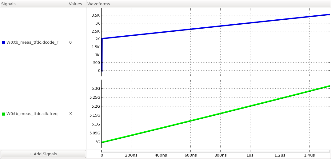
Figure. the digital-to-frequency characteristic of the DCO.