ADC_DeltaSigmaADCOrder2 : A second-order delta-sigma analog-to-digital converter (ADC)
A delta-sigma analog-to-digital converter (DS-ADC) digitizes an analog input to a digital output using a delta-sigma modulation. In particular, this delta-sigma ADC model receives differential analog input signals inp and inn, producing a multi-bit digital output out.
This DS-ADC model is composed of a delta-sigma modulator and a decimation filter. The delta-sigma modulator converts differential analog inputs, inp and inn, into a single-bit digital output stream Dout, and the decimation filter converts this Dout stream into a low-frequency, multi-bit digital stream of out, which corresponds to the final digitized output.
Input/Output Terminals
| Name | I/O | Type | Description |
| oclk | output | wire | output clock |
| out[20:0] | output | wire | digital output |
| ck1 | input | xbit | input clock 1 |
| ck2 | input | xbit | input clock 2 |
| cm | input | xreal | common mode |
| gl_reset | input | wire | global reset |
| inn | input | xreal | analog input (neg) |
| inp | input | xreal | analog input (pos) |
| refn | input | xreal | reference voltage (neg) |
| refp | input | xreal | reference voltage (pos) |
List of Children Cells
| ADC_DeltaSigmaADCOrder2_CTDSM : A continuous-time delta-sigma modulator (CT-DSM) for a second-order delta-sigma ADC |
| ADC_DeltaSigmaADCOrder2_DecimationFilter : A decimation filter for a second-order delta-sigma ADC |
List of Testbenches
| tb_check_sineinput : A testbench for checking the basic operation of an ADC with a sinusoidal input |
tb_check_sineinput : A testbench for checking the basic operation of an ADC with a sinusoidal input
This testbench checks the basic operation of an ADC, by applying differential sinusoidal signals to the inputs inp and inn of the ADC and observing its digital outputs out. The testbench drives the two clock inputs clk1 and clk2 with non-overlapping clocks.
The ADC is expected to produce a digital output corresponding to the same-frequency sinusoid.
`include "xmodel.h"

module tb_check_sineinput (
    output oclk,                    // output clock
    output [20:0] out               // 21-bit output
);

// signal declarations
xbit    clk1;
wire    clk1_XMODELCONN0_BIT;
xbit    clk2;
xreal   cm;
xbit    gl_reset;
wire    gl_reset_XMODELCONN0_BIT;
xreal   inn;
xreal   inp;
xreal   refn;
xreal   refp;

// connector declarations
xbit_to_bit xmodel_conn0_clk1 (.in(clk1), .out(clk1_XMODELCONN0_BIT));
xbit_to_bit xmodel_conn0_gl_reset (.in(gl_reset), .out(gl_reset_XMODELCONN0_BIT));

// instance declarations
ADC_DeltaSigmaADCOrder2 DUT (.inn(inn), .refn(refn), .oclk(oclk), .out(out[20:0]), .inp(inp), .refp(refp), .ck1(clk1), .ck2(clk2), .cm(cm), .gl_reset(gl_reset_XMODELCONN0_BIT));

sin_gen     #(.offset(1), .amp(0.4), .freq(1e+06), .delay(0.0), .damp(0.0), .init_phase(3.14159), .AM_offset(1), .AM_amp(0.0), .AM_freq(0.0), .FM_index(0.0), .FM_freq(0.0)) XP1 (.out(inn));
sin_gen     #(.offset(1), .amp(0.4), .freq(1e+06), .delay(0.0), .damp(0.0), .init_phase(0.0), .AM_offset(1), .AM_amp(0.0), .AM_freq(0.0), .FM_index(0.0), .FM_freq(0.0)) XP0 (.out(inp));
pulse_gen   #(.init_value(1), .delay(2e-09), .width(1), .period(2)) XP10 (.out(gl_reset));
pulse_gen   #(.init_value(0), .delay(5e-11), .width(4.5e-10), .period(1e-09)) XP2 (.out(clk1));
pulse_gen   #(.init_value(0), .delay(5.5e-10), .width(4.5e-10), .period(1e-09)) XP3 (.out(clk2));
dc_gen      #(.value(0.5), .noise(0.0)) XP5 (.out(refn));
dc_gen      #(.value(1.5), .noise(0.0)) XP4 (.out(refp));
dc_gen      #(.value(1), .noise(0.0)) XP7 (.out(cm));

// inline dump statements
initial begin
    $xmodel_dumpfile("xmodel.jez");
    $xmodel_dumpvars("level=0");
end

endmodule
Simulation Results
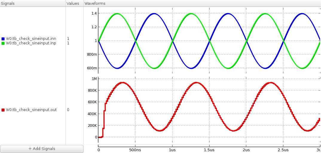
Figure. input and output waveforms.