OSC_LinearDCO : A digitally-controlled oscillator (DCO) with a linear D-to-f characteristic
A digitally-controlled oscillator (DCO) produces an output clock out of which frequency is controlled by a digital input in. In particular, this DCO model describes a DCO with a linear digital-to-frequency characteristic. In other words, the frequency of the output clock out is proportional to the input digital code in, as described by the following equation:
frequency = freq0 + Kdco * (in - in0)
The parameter freq0 sets the nominal frequency of the DCO when the input is at its nominal value set by the parameter in0. And the parameter Kdco denotes the DCO gain, defining the change in the DCO frequency per unit step change in the input code.
This DCO model is described using a dac primitive followed by a freq_to_clk primitive. The dac primitive converts the input digital code to a frequency value and the freq_to_clk primitive produces a clock with the corresponding frequency. The phase noise characteristics of the DCO can be modeled by defining the phase noise parameters of the freq_to_clk primitive, such as PN_fcenter, PN_foffset, PN_dbc, PN_fcorner, and PN_floor. For more information on these parameters, please refer to the documentation on the freq_to_clk primitive.
Input/Output Terminals
| Name | I/O | Type | Description |
| out | output | xbit | output clock |
| in[13:0] | input | bit | input control |
Parameters
| Name | Type | Default | Description |
| in0 | bit | 14’b10000000000000 | nominal input value |
| freq0 | real | 2G | DCO frequency at nominal input value (Hz) |
| Kdco | real | 61.035k | DCO gain (Hz/step) |
| PN_fcenter | real | -1.0 | phase noise center frequency (Hz) |
| PN_foffset | real | 0.0 | phase noise offset frequency (Hz) |
| PN_dbc | real | -`INFINITY | phase noise measured in dBc/Hz (dBc/Hz) |
| PN_fcorner | real | 0.0 | 1f^3 phase noise corner frequency (Hz) |
| PN_floor | real | -`INFINITY | phase noise floor measured in dBc/Hz (dBc/Hz) |
| RJ_kappa | real | 0.0 | RMS accumulated random jitter after 1 second (second) |
| RJ_rms | real | 0.0 | RMS independent random jitter (second) |
List of Testbenches
| tb_meas_tfdc : A testbench for measuring the digital-to-frequency characteristic of a DCO |
tb_meas_tfdc : A testbench for measuring the digital-to-frequency characteristic of a DCO
This testbench measures the digital-to-frequency (D-to-f) characteristic of a DCO by applying a gradually-varying digital input to the DCO and measuring its output frequency.
The measured frequency is expected to change with the digital input code according to the D-to-f equation assumed by the DCO model.
`include "xmodel.h"

module tb_meas_tfdc ();

    bit  [13:0] dcode;      // DCO digital code
    bit  [13:0] inc;        // incremental step
    xbit clk;               // clock signal
    real dcode_r;           // output digital code

    // dcode generator
    initial begin
        dcode = 14'b100000000000;
        inc = 14'b000000000001;

        while (dcode < 14'b111000000000) begin
            #(1e-9/`TIME_SCALE);
            dcode = dcode + inc;
        end

        $finish;
    end

    always @(dcode) dcode_r = real'(dcode);

    // DUT (device-under-test)
    OSC_LinearDCO  DUT(.in(dcode), .out(clk));

    // probing
    probe_real  prb_in(dcode_r);
    probe_freq  prb_freq_lin(clk);

endmodule
Simulation Results
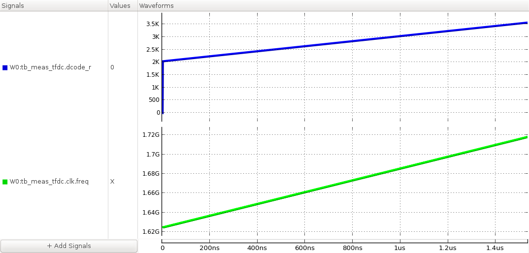
Figure. the digital-to-frequency characteristic of the DCO.