MODELZEN Technology Configuration File
A MODELZEN technology configuration file defines how MODELZEN should map each device element contained in the input circuit netlist to an equivalent XMODEL circuit-level primitive. Since such mapping may be specific to each IC technology or design environment, users may need to write a new technology configuration file when the target IC technology or design environment changes. With the technology configuration file, one can also override the default MODELZEN option values described in Section 3 so that one can avoid having to type the same option values over and over every time she or he starts a new MODELZEN session.
A MODELZEN technology configuration file itself is a Python script defining a set of predefined variables with their option values. A sample technology configuration file can be found in ${XMODEL_HOME}/etc/tech_config.py where ${XMODEL_HOME} denotes the XMODEL installation directory. An advantage of using this Python format is that one can embed scripts within the technology configuration file to define some of the option values in a programmatic fashion and reduce laborious work. Please refer to the various documentations on Python scripting language for more detailed description on the grammatical syntaxes used in the technology configuration file.
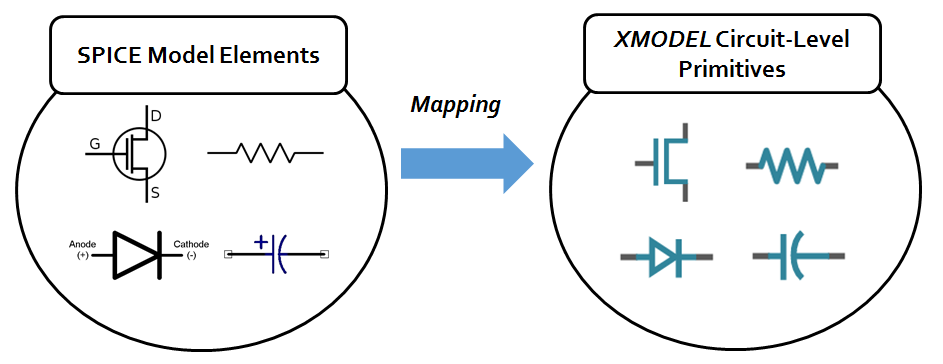
Figure 12. The mapping defined the MODELZEN technology configuration file.
A typical MODELZEN technology configuration file consists of the following five sections: importing default configuration, defining SPICE simulation options, defining device models and corners, defining device mapping, and overriding default MODELZEN options. This section will describe each of them in detail.
Importing Default Configuration
It is recommended that a technology configuration file start with an import statement that inherits the default option values defined in the default_config.py file located in the ${XMODEL_HOME}/etc directory.
#----------------------------------------------------------------
# import modules
#----------------------------------------------------------------

from default_config import *
NOTE: Users are advised not to modify this default configuration file directly. Some of the option values defined in the ${XMODEL_HOME}/etc/default_config.py are subject to change without notice when they are deemed necessary to improve MODELZEN. Inheriting the default option values via importing rather than copying them ensures that your technology configuration file can stay up-to-date with the latest features of MODELZEN. If you need to set up a site-wise default configuration for your own organization, it is advised to write a new configuration file that imports default_config.py as-is and overrides its option parameters as explained below. The other project-specific configuration files can then import your site-wise default configuration.
Defining SPICE Simulation Option
This section defines how MODELZEN should run SPICE simulation in the user’s environment. In fact, this section overrides the default XMULAN options defined in the ${XMODEL_HOME}/etc/default_config.py file.
#----------------------------------------------------------------
# simulator configurations
#----------------------------------------------------------------

# command statements
sim_cmd['hspice'] = lambda deck, log, outdir: ['hspice', '-i', deck, '-o', log]

# simulator option statements
sim_option['hspice'] = """\
.option post_version=9605
.option accurate post
.option measdgt=8
"""
For instance, in the sample technology configuration file listed above, sim_cmd[simulator] defines a function that generates a command that launches a simulation with three arguments: input filename (deck), log filename (log) and directory to store the output results (outdir). The dictionary key simulator can be one of the simulators supported by XMULAN (e.g. hspice, spectre, finesim, …). The return value of the function must be a list of tokens to be passed to the shell interpreter. In other words, in order to pass additional option arguments to the SPICE simulator command, add those arguments additional elements to this list.
For example, if your site uses a wrapper script called "/cad/bin/run_hspice" to launch HSPICE simulations, you may modify this sim_cmd definition as below:
 # command statements
sim_cmd['hspice'] = lambda deck, log, outdir: ['/cad/bin/run_hspice', '-i', deck, '-o', log]
If you want to pass additional option arguments, e.g., "--queue long", which is made of two argument tokens, append them as additional elements in the returned list as below:
# command statements
sim_cmd['hspice'] = lambda deck, log, outdir: ['/cad/bin/run_hspice', '-i', deck, '-o', log, '--queue', 'long']
Note that appending --queue and long as two separate elements is different from appending them one element --queue long. The former is considered as two tokens while the latter is considered as one token including the space in-between. That is, the latter is equivalent to passing "--queue long" enclosed by quotation marks to the UNIX shell.
The sim_option[simulator] defines the option statements inserted into the simulation deck. It is typically a multi-line string enclosed by a pair of """. You can define the simulation options such as the format of the result files, precision of the recorded results, etc. In fact, since this is a string that is directly inserted into the characterization simulation decks, you can insert any additional statements necessary to run simulations in your environment.
Defining Device Models and Corners
This section defines the SPICE device models and their corner conditions. Specifically, it defines two dictionary variables indexed by the simulator name: dev_corner and dev_model.
#----------------------------------------------------------------
# device models and PVT/MC corners
#----------------------------------------------------------------
# list of predefined PVT corners
dev_corner['hspice'] = { \
    "TTTT" : dict(proc='TT', volt=1.0, temp=25),
    "FFFF" : dict(proc='FF', volt=1.1, temp=-30),
    "SSSS" : dict(proc='SS', volt=0.9, temp=125),
}

# list of device model statements
dev_model['hspice'] = { \
    "PVT_corner" : """\
.protect
.lib "/cad/tech/cmos065/model/hspice/spice_model.l" @proc
.param supply='2.5*@volt'
.temp @temp
.unprotect
""",
    "MC_local" : None,
    "MC_global" : None,
    "MC_local+global" : None,
}

# default device model statement
dev_corner['hspice']['default'] = dev_corner['hspice']['TTTT']
dev_model['hspice']['default'] = dev_model['hspice']['PVT_corner']
The dev_model dictionary defines a set of statements to be included in the SPICE simulation deck to specify the SPICE model libraries and their conditions. For instance, in the above example, dev_model["hspice"]["PVT_corner"] defines the model statements when running a corner-based simulation with HSPICE.
Note that the model statement string defining dev_model["hspice"]["PVT_corner"] in the above example contains three embedded Python variables: @proc, @volt, and @temp. In fact, users can use a full-featured embedded Python language in this string, allowing a programmable description of model statements using these variables. For more description on embedded Python, please refer to this website: http://www.alcyone.com/software/empy. For simple usage, you can embed Python variables in the string by putting @ in front of the variable name.
# list of device model statements
dev_model['hspice'] = { \
    "PVT_corner" : """\
.protect
.lib "/cad/tech/cmos065/model/hspice/spice_model.l" @proc
.param supply='2.5*@volt'
.temp @temp
.unprotect
""",
    "MC_local" : None,
    "MC_global" : None,
    "MC_local+global" : None,
}
In the above example, the dev_model dictionary also has other keys such as "MC_local", "MC_global", and "MC_local+global", which are reserved for cases of running Monte-Carlo simulations with local variation, global variation, and both variations, respectively. Currently, they are not used by MODELZEN.
The dev_corner dictionary defines the values of the embedded Python variables used in the dev_model string indexed by a single tag. Typically, this tag indicates the simulation corner (e.g. "TTTT").
# list of predefined PVT corners
dev_corner['hspice'] = { \
    "TTTT" : dict(proc='TT', volt=1.0, temp=25),
    "FFFF" : dict(proc='FF', volt=1.1, temp=-30),
    "SSSS" : dict(proc='SS', volt=0.9, temp=125),
}
For instance, the dev_corner in the above example uses proc of TT, volt of 1.0, and temp of 25 (each denoting process condition, voltage value, and temperature value, respectively) for a corner named "TTTT". On the other hand, for a corner named "FFFF", it uses proc of "FF", volt of 1.1, and temp of -30. Users can choose their own names for the corner names and own set of variables used in the model statements. This offers high flexibility in describing various simulation conditions encountered in modern IC technologies.
The default values in the dev_model[simulator] and dev_corner[simulator] dictionaries define the default model statements and default variable values to be used by MODELZEN when characterizing the devices via SPICE simulation.
# default device model statement
dev_corner['hspice']['default'] = dev_corner['hspice']['TTTT']
dev_model['hspice']['default'] = dev_model['hspice']['PVT_corner']
Defining Device Mapping
This section defines the mapping between the SPICE-level devices and XMODEL primitives, which is one of the most important information used by MODELZEN.
The device mapping section in the sample technology configuration file is listed below. The section defines a set of dictionary-typed variables: devo_devicemap, devo_subcktmap, devo_instmap, and devo_namemap. For basic usage, you only need to define devo_devicemap.
#----------------------------------------------------------------
# device characterization options (devo)
#----------------------------------------------------------------

# device mapping table
devo_devicemap = {
    "nmos" : dict(type="nmosfet", prefix="M",
                    level_dc="pwl", level_ac=1, vmax=1.2, vmin=0.0),
    "pmos" : dict(type="pmosfet", prefix="M",
                    level_dc="pwl", level_ac=1, vmax=1.2, vmin=0.0),
    "polyres" : dict(type="resistor", prefix="R",
                    level_dc="linear", level_ac=0),
    "momcap" : dict(type="capacitor", prefix="C",
                    level_dc="linear", level_ac=0),
}

# subckt mapping table
devo_subcktmap = {
    "my_inv" : {
        "nmos" : dict(type="nmosfet", prefix="M",
                    level_dc='max_idsat', level_ac=1, vmax=1.2, vmin=0.0),
        "pmos" : dict(type="pmosfet", prefix="M",
                    level_dc='max_idsat', level_ac=1, vmax=1.2, vmin=0.0),
    }
}

# instance mapping table
devo_instmap = {
    "subckt1:inst1" : dict(type="nmosfet",
                       level_dc='pwl:3', level_ac=3, vmax=1.2, vmin=0.0),
    "subckt2:inst2" : dict(type="open"),
}

# net/instance name translation
devo_namemap = [
    dict(pattern=r'!', replace=r''),
    dict(pattern=r'\\<', replace=r'<'),
    dict(pattern=r'\\>', replace=r'>'),
]
Global Device Mapping
The devo_devicemap defines the mapping between the technology-specific SPICE device models and XMODEL primitives. It is a Python dictionary that maps each of the SPICE device model names to a set of MODELZEN attributes. For instance, in the above example, the line:
"nmos"  : dict(type="nmosfet", prefix="M",
            level_dc="pwl", level_ac=1, vmax=1.2, vmin=0.0),
indicates that the nmos device in the input netlist will be treated and characterized as an "nmosfet" primitive in XMODEL. The currently available XMODEL primitives include: resistor, capacitor, inductor, open, short, diode, nmosfet, and pmosfet as listed in Table 7.
Table 7. Listing of the XMODEL primitive types available for device mapping.
| Primitives | Descriptions |
open |
Open-circuit element |
short |
Short-circuit element |
resistor |
Resistor |
capacitor |
Capacitor |
inductor |
Inductor |
diode |
Diode |
nmosfet |
N-type MOSFET |
pmosfet |
P-type MOSFET |
The rest of the parameters such as prefix, vmax, level_dc, level_ac, vmax, vmin, etc., define how MODELZEN should perform SPICE characterization and model fitting on the device model. Table 8 below provides the description on the common set of parameters used by most of the primitives.
Table 8. Listing of device mapping option parameters.
| Parameters | Descriptions |
prefix |
SPICE prefix to be prepended to the device instance name for SPICE characterization. |
level_dc |
The accuracy level of DC model, i.e. I-V characteristics. It has a string-typed value (e.g. "ideal", "linear", "pwl", etc.). |
level_ac |
The accuracy level of AC model, e.g. C-V characteristics. It has an integer-typed value (e.g. 0~3). The higher value implies higher accuracy. 0 implies no capacitances at all. |
vmax |
Maximum voltage range (often the device’s rated voltage level). |
vmin |
Minimum voltage range (often 0V). |
The prefix parameter sets the SPICE prefix to be prepended to the device instance name during SPICE characterization. This information is necessary since in SPICE netlists, the first letter of the instance name (i.e., the prefix) specifies whether the foundry-provided device model is described using one of SPICE built-in models (e.g. ‘M’ for MOSFET, ‘Q’ for bipolar junction transistors, ‘D’ for diodes, ‘R’ for resistors, ‘C’ for capacitors, etc.) or using a subcircuit (‘X’). You can define this as blank (“”) if your input netlist already has the correct prefixes for the instances.
The level_dc parameter sets the accuracy level of the DC model of the device, i.e., the I-V characteristics. The level_dc parameters for linear and ideal primitives have little meaning as they are fixed to either "linear" or "ideal". For instance, the level_dc parameter for a linear, passive primitive such as resistor, capacitor, and inductor is fixed to "linear" and that for an ideal primitive such as open and short is fixed to "ideal". In fact, users may leave this parameter undefined for linear and ideal primitives.
On the other hand, the level_dc parameter for a nonlinear primitive such as diode, nmosfet, and pmosfet deserves a special attention. MODELZEN basically fit the I-V characteristics of a nonlinear device to a piecewise-linear (PWL) model and the level_dc parameter specifies the number of segments (or knots) to be used in this PWL model and the error to be minimized while performing the model fitting. Table 9 lists the supported level_dc parameter values for nonlinear devices.
Table 9. Listing of available level_dc parameter values for nonlinear devices.
| Values | Description |
pwl_abs:N |
Fit the I-V curve to an N-knot piecewise linear (PWL) model that minimizes the absolute RMS error. N is an integer greater than or equal to 1. For instance, "pwl_abs:3". |
pwl_rel:N |
Fit the I-V curve to an N-knot piecewise linear (PWL) model that minimizes the relative RMS error. N is an integer greater than or equal to 1. For instance, "pwl_rel:3". |
pwl:N |
Same as pwl_rel:N. |
pwl |
Same as pwl:2. |
max_idsat |
Same as pwl_abs:1. |
max_gmid |
Same as pwl_rel:1 or pwl:1. |
The criteria used for PWL model fitting for nonlinear devices in MODELEN are either to minimize the root-mean-squared (RMS) error measured in absolute quantities or to minimize the RMS error measured in relative quantities. In other words, MODELZEN minimizes the RMS value of either  or
or  where
where  is the fitted value and
  is the true value. This error is measured over a voltage range defined by the parameters
 vmin and vmax. For instance, "pwl_abs:3" fits the nonlinear I-V curve of a device to a 3-knot PWL model while minimizing the absolute RMS error and "pwl_rel:2" fits to a 2-knot PWL model while minimizing the relative RMS error. There are also some shorthands available for commonly-used option values; for instance, "pwl" is the same as "pwl_rel:2", "max_gmid" the same as "pwl_rel:1", and "max_idsat" the same as "pwl_abs:1".
Whether to use the absolute or relative error for PWL model fitting depends on the operation of the device. Figure 13 illustrates the effects of using different level_dc values for an N-type MOSFET device, where the I-V characteristic of interest is the IDS-VGS curve. Generally, it is desirable to use a PWL model with the least number of knots while attaining the accuracy in the operating range of interest.
For example, for MOSFET devices used in most CMOS static logic gates, the recommended level_dc parameter value is "max_idsat". The resulting model tends to achieve good fitting accuracy where the drain saturation current (ID,SAT) is high, the primary factor that determines the delay of most logic gates. While using only one knot for the IDS-VGS PWL model may result in a large error near the device threshold, it achieves the fastest simulation speed with minimal impacts the timing accuracy.
On the other hand, for MOSFET devices used in analog circuits such as amplifiers, the recommended level_dc parameter value is "pwl". Minimizing the relative RMS error tends to improve the accuracy where the gm/IDS ratio is large, the operating condition that most analog circuits strive to achieve, as it is the condition that yields the highest gain-bandwidth product for a given power consumption. However, as illustrated in Figure 13, using only one knot (i.e. "pwl_rel:1") cannot model the dependence of transconductance (gm) on VGS at all. The level_dc of "pwl" , i.e., "pwl_rel:2", is a good compromise between the model accuracy and simulation speed.
One can apply different device mapping options to different circuits or devices using the devo_subcktmap and devo_instmap options in the technology configuration file or the MODELZEN properties annotated from schematics via a design information file. The devo_subcktmap and devo_instmap options are described in this Section and the use of MODELZEN properties is described in Section 5.
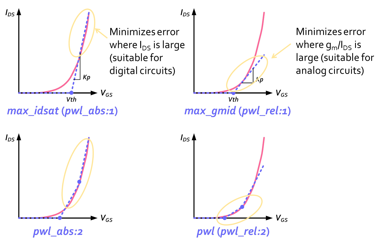
Figure 13. Illustration of various level_dc parameter values available for MOSFET devices.
On the other hand, the level_ac parameter sets the accuracy level of the AC model of the device, such as the C-V characteristics. Table 10 lists the available values of this parameter for MOSFET devices and Figure 14 illustrates their meanings. The level_ac parameter takes an integer-typed value starting from 0 where the higher value implies the higher accuracy and 0 implies no capacitances characterized at all.
The recommended value of level_ac parameter for most transistors used in either analog or digital circuits is 1, which is a good compromise between the modeling accuracy and simulation speed. Users can use level_ac of 0 for selected devices of which transient behavior is of little interest and use level_ac of 3 for devices of which coupling capacitance makes paramount difference on the circuit behavior (e.g. Miller effect).
Table 10. Listing of available level_ac parameter values for MOSFET devices.
| Values | Description |
0 |
No capacitances are characterized at all. |
1 |
The capacitances of the device are characterized as a set of equivalent capacitances between each terminal and ground. |
2~3 |
The capacitances are characterized both as grounded capacitances and coupling capacitances between the terminals. This is the most accurate model, but can slow down the simulation speed. |
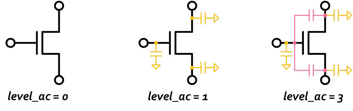
Figure 14. Available level_ac parameter values for MOSFET devices.
Table 11 summaries the available level_dc and level_ac parameter values for each different XMODEL primitive. The list of XMODEL primitives available for device mapping and modeling options is expected to grow in the future versions of MODELZEN.
Table 11. Listing of available level_dc and level_ac parameter values for each XMODEL primitive.
| Primitive | level_dc | level_ac |
open, |
"ideal" |
0 |
resistor |
"linear" |
0, 1 |
diode |
"pwl_abs:N", "pwl_rel:N", "pwl:N", "pwl", "max_idsat", "max_gmid" |
0, 1, 2 |
nmosfet, |
"pwl_abs:N", "pwl_rel:N", "pwl:N", "pwl", "max_idsat", "max_gmid" |
0, 1, 2, 3 |
Subcircuit-Specific Device Mapping
As previously mentioned, the devo_subcktmap dictionary allows one to use a dedicated device mapping for selected subcircuits. For instance, you can control the types and accuracy levels differently for the devices contained in the analog circuits or digital circuits. For instance, the following example defines a dedicated device mapping for a subcircuit named "my_inv":
# subckt mapping table
devo_subcktmap = {
    "my_inv" : {
        "nmos" : dict(type="nmosfet", prefix="M",
                    level_dc='max_idsat', level_ac=1, vmax=1.2, vmin=0.0),
        "pmos" : dict(type="pmosfet", prefix="M",
                    level_dc='max_idsat', level_ac=1, vmax=1.2, vmin=0.0),
    }
}
In case when you want to use a common device mapping for more than one subcircuits (e.g. a set of logic gate cells), it may be convenient to define the mapping dictionary as a new variable and use it when defining devo_subcktmap, for instance:
# device mapping for digital logic gates
devicemap_logic = {
    "nmos" : dict(type="nmosfet", prefix="M",
                level_dc='max_idsat', level_ac=1, vmax=1.2, vmin=0.0),
    "pmos" : dict(type="pmosfet", prefix="M",
                level_dc='max_idsat', level_ac=1, vmax=1.2, vmin=0.0),
}

# subckt mapping table
devo_subcktmap = {
    "my_inv" : devicemap_logic,
    "my_nand" : devicemap_logic,
    "my_nor" : devicemap_logic,
    "my_xor" : devicemap_logic,
}
Or, perhaps more compactly:
# device mapping for digital logic gates
devicemap_logic = {
    "nmos" : dict(type="nmosfet", prefix="M",
                level_dc='max_idsat', level_ac=1, vmax=1.2, vmin=0.0),
    "pmos" : dict(type="pmosfet", prefix="M",
                level_dc='max_idsat', level_ac=1, vmax=1.2, vmin=0.0),
}

# list of logic cells
list_logic = ["my_inv", "my_nand", "my_nor", "my_xor"]

# subckt mapping table
for cell in list_logic:
    devo_subcktmap[cell] = devicemap_logic
These examples illustrate that one can use various Python expressions to define the technology configuration options in a programmatic fashion.
Instance-Specific Device Mapping
On the other hand, the devo_instmap dictionary allows one to define instance-specific mapping overriding the global or subcircuit-specific device mappings. For instance, one can force a certain transistor to be ignored by mapping it to an "open" primitive. The following example demonstrates the case of mapping an instance named "inst1" of a subcircuit named "subckt1" to an nmosfet primitive with the higher values of level_dc and level_ac parameters and ignoring an instance named "inst2" of a subcircuit named "subckt2" as an open-circuit element. Note that in case of mapping a device to a different type of primitive (e.g. mapping a transistor to a diode or capacitor), it is necessary to define the instance terminal mapping as well, using the instterms parameter.
# instance mapping table
devo_instmap = {
    "subckt1:inst1" : dict(type="nmosfet",
                       level_dc='pwl:3', level_ac=3, vmax=1.2, vmin=0.0),
     "subckt2:inst2" : dict(type="open"),
}
Wildcard and Regular Expression Matching
The aforementioned devo_devicemap, devo_subcktmap, and devo_instmap are dictionaries that map each of the device name, subcircuit name, and instance name to its device mapping property set, respectively.
When your device names, subcircuit names, or instance names have certain regularities, you can use wildcard expressions (e.g., * and ?) or regular expressions to define the mapping in a more compact form.
The wildcard() function allows one to define a name pattern expressed by UNIX-shell wildcard characters such as * and ?. For example, the example below maps any device with a name starting with "nch" to an nmosfet primitive and also maps any device with a name starting with "pch" and followed by one arbitrary character to an pmosfet primitive.
devo_devicemap = {
    wildcard("nch*") : dict(type="nmosfet", prefix="M",
                            level_dc="max_idsat", level_ac=1, vmax=1.2),
    wildcard("pch?") : dict(type="pmosfet", prefix="M",
                            level_dc="max_idsat", level_ac=1, vmax=1.2),
}
For more information on the wildcard expressions supported by the wildcard() function, one can refer to the documentation on Python’s fnmatch library.
On the other hand, the regex() function allows one to define a name pattern using regular expressions. For instance, the example below uses a subcircuit-specific mapping defined by devicemap_logic for subcircuits of which names start with STD_INV or STD_NAND and followed by at least one number literal.
devo_subcktmap = {
    regex(r"STD_(INV|NAND)[0-9]+") : devicemap_logic,
}
For more information on the regular expressions supported by the regex() function, one can refer to the documentation on Python’s re library.
Net/Instance Name Translation
Lastly, one can define net/instance name translation between the netlists and models using the devo_namemap list. For instance, with the following option settings, MODELZEN will strip all "!" characters, replace "\ <" and "\ >" with "<" and ">", respectively. Such name translations are often required to deal with global signal names like "vdd!" and "gnd!", and bus names like "A\<0\>", respectively.
Each dictionary item in the devo_namemap list contains a pattern and replace keys, where the pattern value is the regular expression for the string being searched and the replace field is the string to be replaced with. In fact, these keys correspond to the pattern and repl arguments of the re.sub() function in the Python regular expression (re) library, respectively. You can also add the optional count and flags arguments to each dictionary item.
# net/instance name translation
devo_namemap = [
    dict(pattern=r'!', replace=r''),
    dict(pattern=r'\\<', replace=r'<'),
    dict(pattern=r'\\>', replace=r'>'),
]
Overriding MODELZEN Default Options
MODELZEN offers many options, controlling how to interpret the input netlists, how to process them, and how to generate the equivalent models in XMODEL. For instance, one may wish to convert all signal names to uppercase letters. To do so, one needs to pass the "--upper" option in the command line or check the "All uppercase" option in the GUI window. Sometimes, it may be cumbersome to specify these options every time you run MODELZEN.
You can override the default MODELZEN options using the technology configuration file. The factory default options are defined in the ${XMODEL_HOME}/etc/default_config.py. The content of the file defining the default MODELZEN options is listed here for your reference.
#----------------------------------------------------------------
# device characterization options (devo)
#----------------------------------------------------------------
# devo options
devo_options = dict(
    output_file = None,
    output_dir = None,
    format = 'cdl',
    uppercase = False,
    lowercase = False,
    config_file = None,
    dbinfo_file = None,
    sim_dir = './modelgen.sim',
    merge_bus = None,
    gbl_module = 'GLOBAL',
    top_module = '__TOP__',
    supply_int = {},
    supply_nets = [],
    level1 = 1.0,
    level0 = 0.0,
    thres1 = 0.5,
    thres0 = 0.5,
    strength = None,
    modules_wire = {},
    modules_xbit = {},
    modules_expand = [],
    ext_params = {},
    mod_prefix = '',
    ignore_pindir = True,
    use_portmacros = True,
    use_splitbus = False,
    merge_dev = ['parallel', 'serial'],
    reduce_dev = ['nmosfet->capacitor', 'pmosfet->capacitor',
               'nmosfet->diode', 'pmosfet->diode'],
    trim_dev = ['R>1e9', 'R<1.0'],
    thread = 1,
    force_sim = False,
    verbose = True,
    log_file = "modelzen.log",
)
The mappings between the variable names and MODELZEN options are self-explanatory in most cases, but are listed in the following table for clarity.
Table 12. The mapping between the technology configuration variables and MODELZEN options.
| Variables | Corresponding MODELZEN Options |
output_file |
--output FILENAME |
output_dir |
--output-dir DIRPATH |
format |
--format FORMAT |
uppercase |
--upper |
lowercase |
--lower |
config_file |
--config FILENAME |
dbinfo_file |
--dbinfo FILENAME |
sim_dir |
--simdir DIRPATH |
merge_bus |
--merge FORMAT |
gbl_module |
--global MODULENAME |
top_module |
--topmodule MODULENAM |
supply_int |
--supply NAME=VALUE |
supply_nets |
--supply NAME |
level1 |
--level1 VALUE |
level0 |
--level0 VALUE |
thres1 |
--thres1 VALUE |
thres0 |
--thres0 VALUE |
strength |
--strength VALUE |
modules_wire |
--wire MODULENAME=SUPPLY |
modules_xbit |
--xbit MODULENAME=SUPPLY |
modules_expand |
--expand MODULENAME |
ext_params |
--param NAME=VALUE |
mod_prefix |
--mod-prefix PREFIX |
ignore_pindir |
--ignore-pindir |
use_portmacros |
--use-portmacros |
use_splitbus |
--use-splitbus |
merge_dev |
--enable-merge CONDITION or --disable-merge CONDITION |
reduce_dev |
--enable-reduce CONDITION or --disable-reduce CONDITION |
trim_dev |
--enable-trim CONDITION or --disable-trim CONDITION |
thread |
--thread NUM_THREADS |
force_sim |
--force |
verbose |
--verbose |
log_file |
--log FILENAME |
As previously noted, it is not advisable to modify the file default_config.py directly when you need to override the default values (the modifications will be lost when you install a new release of MODELZEN!). The recommended way is to selectively override them in the technology configuration file after importing default_config.py.
For instance, to convert all characters in the input netlists to uppercase by default, you can simply insert the following line in your own technology configuration file:
 # devo options
devo_options['uppercase'] = True
Or, to merge only parallel-connected devices but not the series- connected devices:
devo_options['merge_dev'] = ['parallel']
To trim shunt resistors with values greater than 1 Mohms instead of the default 1 Gohms and trim series resitors with values less than 0.1 instead of default 1.0:
devo_options['trim_dev'] = ['R>1e6', 'R<0.1']
To expand subcircuits named xyz during the topology analysis:
devo_options['modules_expand'] = ['xyz']
Again, using the Python language for setting these options provides high flexibility.