TDC_DelayLineTDC : A delay-line-based time-to-digital converter (TDC)
A time-to-digital converter (TDC) measures the timing difference between two input signals clk_fb and clk_ref and produces the output out expressing the result in a digital format. A delay-line-based TDC digitizes the timing difference between the two input clocks by sampling clk_ref with a set of triggering clocks derived from a delay line propagating clk_fb. This type of TDC is analogous to a flash-type ADC which digitizes its analog input by simultaneously comparing it with a set of thresholds.
This delay-lined-based TDC model is described with a set of delay_xbit and dff_xbit primitives. One of the input clock clk_fb propagates through a chain of delay_xbit primitives each having a delay equal to delay_lsb and produces a set of triggering clocks fbclk. Each of fbclk triggers a D-flipflop sampling the delayed version of the other input clock clk_ref called rclk. The encoder logic described by an inline primitive converts the resulting thermometer-coded D-flipflop outputs pd to a binary output out. The parameter delay_lsb sets the unit stage delay of the delay line and defines the resolution of the TDC. The parameter delay_min sets the delay applied to the clock clk_ref and determines the minimum range of the TDC.
Input/Output Terminals
| Name | I/O | Type | Description |
| out[3:0] | output | bit | output |
| clk_fb | input | xbit | feedback clock |
| clk_ref | input | xbit | reference clock |
Parameters
| Name | Type | Default | Description |
| out_min | int | -8 | minimum output range |
| delay_lsb | real | 64p | delay resolution |
| delay_min | real | delay_lsb*out_min | minimum delay range |
List of Testbenches
| tb_meas_tfdc : A testbench for measuring the timing error vs. output transfer characteristics of a time-to-digital converter (TDC) |
tb_meas_tfdc : A testbench for measuring the timing error vs. output transfer characteristics of a time-to-digital converter (TDC)
This testbench measures the timing error vs. output transfer characteristics of a time-to-digital converter (TDC) by gradually changing the timing difference applied to the TDC’s two inputs. A probe_dc primitive sweeps the timing error and measures the TDC’s digital output assuming it is in two’s complement representation. The result shows the digital output code produced for each interval of the input timing difference.
Simulation Results
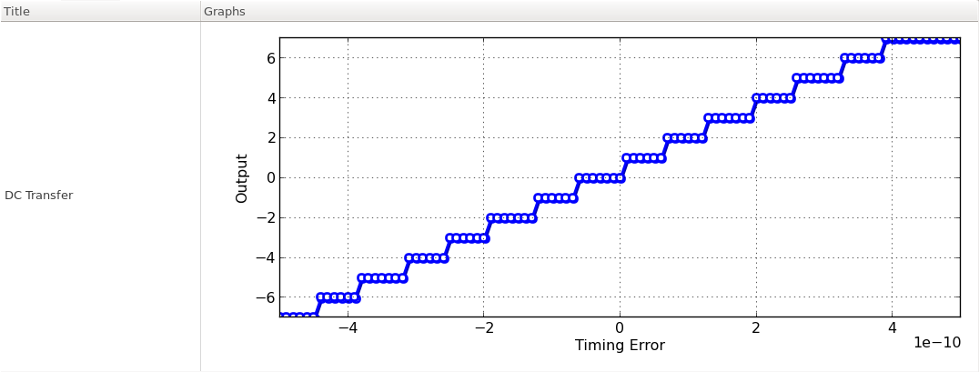
Figure. timing error vs. output transfer characteristics.