PLL_DigitalPLL : A digitally-controlled phase-locked loop (PLL)
A phase-locked loop (PLL) is a feedback system that generates an output clock of which phase is aligned with that of the input clock. In particular, a digitally-controlled PLL is a PLL that uses a digital controller as its loop filter which updates the oscillator phase and frequency in response to the phase error measured by the phase detector. This type of PLL is gaining popularity due to its programmability and robustness against circuit non-idealities.
This digitally-controlled PLL model is composed of a time-to-digital converter (TDC), a digital loop filter, a digitally-controlled oscillator (DCO), and a frequency divider. The TDC detects the timing error between the input clock in and feedback clock fb and produces a 4-bit digital value terr. The digital loop filter then processes this value and adjusts its 12-bit digital output dctrl, controlling the frequency and phase of the DCO output clock out. When a frequency divider with a dividing ratio of N is present in the feedback path, the PLL generates an N-times higher-frequency output clocks out than the input clock in.
Input/Output Terminals
| Name | I/O | Type | Description |
| out | output | xbit | output clock |
| in | input | xbit | input clock |
| reset | input | wire | reset signal |
Parameters
| Name | Type | Default | Description |
| init_value | int | 12’b1000_0000_0000 | initial frequency code |
List of Children Cells
| DIV_SyncDividerBy16 : A synchronous divide-by-16 frequency divider |
| OSC_ExpDCO : A digitally-controlled oscillator (DCO) with an exponential D-to-f characteristic |
| PLL_DigitalPLL_LoopFilter : A digital loop filter for digitally-controlled PLL |
| TDC_GatedOscTDC : A gated-oscillator-based time-to-digital converter (TDC) |
List of Testbenches
| tb_check_lock : A testbench for checking the locking behavior of a PLL |
| tb_meas_freqstep : A testbench for measuring the frequency step response of a PLL |
| tb_meas_jhist : A testbench for measuring the jitter histogram of a PLL output clock |
| tb_meas_jtran : A testbench for measuring the jitter transfer characteristics of a PLL |
| tb_meas_phasestep : A testbench for measuring the phase step response of a PLL |
tb_check_lock : A testbench for checking the locking behavior of a PLL
This testbench checks if a phase-locked loop (PLL) can successfully acquire a lock by simulating its locking transient. The testbench applies a fixed-frequency reference clock to the PLL, of which initial frequency starts from a value far from the desired lock position. The frequency and phase trajectories of the PLL output clock indicate whether the PLL has the capability of acquiring the correct lock when it is started from the said initial condition.
`include "xmodel.h"

module tb_check_lock();

    parameter real ref_freq = 312.5e6;  // reference frequency

    // variables
    xbit clk_ref;                       // reference clock
    xbit clk_out;                       // output clock
    bit reset;

    // reference clock generator
    clk_gen     #(.freq(ref_freq)) clk_gen(clk_ref);

    //reset
    initial begin
        reset = 1;
        #(20ns) reset = 0;
    end

    // DUT (device-under-test) digital PLL
    PLL_DigitalPLL  #(.init_value(12'b0010_0000_0000)) DUT (.in(clk_ref), .out(clk_out), .reset(reset));

    // probing
    probe_xbit  probe_ref(clk_ref);
    probe_xbit  probe_out(clk_out);
    probe_freq  probe_freq(clk_out);
    probe_phase #(.freq(ref_freq*16), .phase_wrap(0)) probe_phase(clk_out);

endmodule
Simulation Results
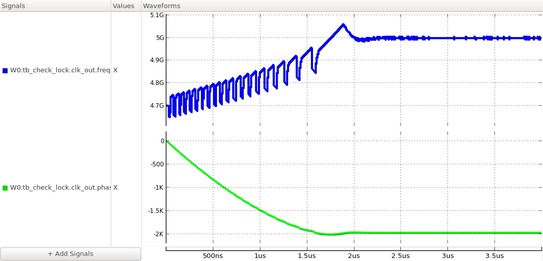
Figure. locking transients of the output clock’s frequency and phase.
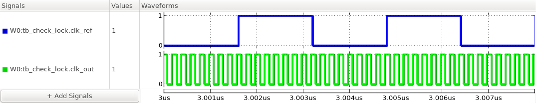
Figure. steady-state waveforms of the input and output clocks.
tb_meas_freqstep : A testbench for measuring the frequency step response of a PLL
This testbench measures the response of a PLL to a step change in its input clock frequency. Once the PLL acquires a lock, the testbench applies a step change in its input clock frequency using the step_gen and freq_to_clk primitives. The responses in the output clock frequency and phase indicate the loop bandwidth and stability of the PLL.
`include "xmodel.h"

module tb_meas_freqstep();

    parameter real ref_freq = 312.5e6;  // reference clock initial frequency
    parameter real freq_step = 3.125e6; // frequency step amount
    parameter real delay = 1e-6;        // A point to make frequency step

    // variables
    `xbit(clk_ref);                     // reference clock
    `xbit(clk_out);                     // output clock

    bit reset;
    `xreal(freq);                       // frequency with step change

    // frequency step generator
    step_gen     #(.init_value(ref_freq), .change(freq_step), .delay(delay))
                 freq_gen(freq);

    // reference clock generaor
    freq_to_clk  clk_ref_gen(.in(freq), .out(clk_ref));

    //reset
    initial begin
        reset = 1;
        #(20ns) reset = 0;
    end

    // DUT (device-under-test) digital PLL
    PLL_DigitalPLL   DUT(.in(clk_ref), .out(clk_out), .reset(reset));

    // probing
    probe_xbit   probe_ref(clk_ref);
    probe_xbit   probe_out(clk_out);
    probe_freq   probe_freq(clk_out);
    probe_freq   probe_ref_freq(clk_ref);

endmodule
Simulation Results
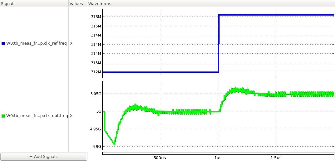
Figure. frequency step response of the PLL.
tb_meas_jhist : A testbench for measuring the jitter histogram of a PLL output clock
This testbench measures the jitter histogram and phase noise spectrum of the output clock of a phase-locked loop (PLL). The testbench first lets the PLL acquire a lock by applying a fixed-frequency clock input and waiting for the PLL responses to settle. Then it collects the output clock transitions and analyzes the jitter histogram and phase noise spectrum. The jitter histogram shows the probability density function of the clock edge position and the phase noise spectrum shows the frequency content of the jitter or phase noise. The jitter and phase noise of a PLL output clock can be contributed by the noise from the input clock and internal components.
`include "xmodel.h"

module tb_meas_jhist();

    parameter real freq_ref = 312.5e6;  // reference clock frequency
    parameter real RJ_rms = 10e-12;     // reference clock random jitter (RMS)
    parameter real t_lock = 1e-6;       // time required for PLL to lock

    xbit clk_ref;                       // reference clock
    xbit clk_out;                       // output clock
    bit reset;

    //reset
    initial begin
        reset = 1;
        #(20ns) reset = 0;
    end

    // DUT phase-locked loop
    PLL_DigitalPLL  DUT(.in(clk_ref), .out(clk_out), .reset(reset));

    // reference clock generator
    clk_gen     #(.freq(freq_ref), .RJ_rms(RJ_rms))
                clk_gen(clk_ref);

    // probing
    probe_xbit  #(.start(t_lock)) probe_out(clk_out);

endmodule
Simulation Results
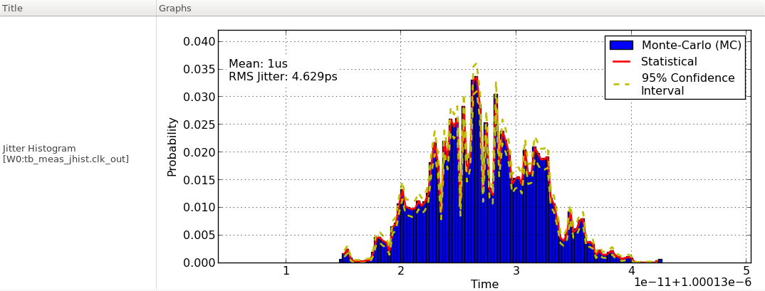
Figure. jitter histogram of the PLL output clock.
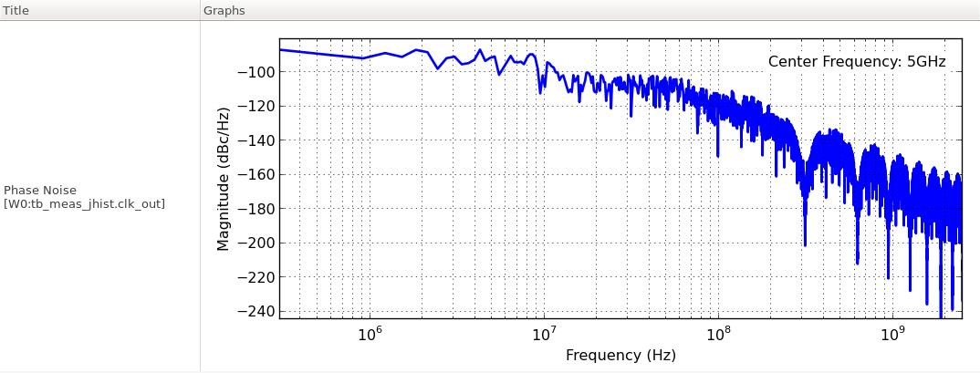
Figure. phase noise spectrum of the PLL output clock.
tb_meas_jtran : A testbench for measuring the jitter transfer characteristics of a PLL
This testbench measures the jitter transfer characteristics of a phase-locked loop (PLL). The testbench measures the jitter transfer function at each frequency by applying a sinusoidal jitter to the input clock using a clk_gen primitive and measuring the magnitude and phase of the resulting sinusoidal response in the output clock phase. The jtran.py script repeats this measurement while sweeping the sinusoidal jitter frequency and constructs the overall jitter transfer function of the PLL.
`include "xmodel.h"

module tb_meas_jtran();

    parameter real ref_freq = @ref_freq;    // input clock frequency
    parameter real SJ_amp = @sj_amp;        // input sinusoidal jitter amplitude in UI
    parameter real SJ_freq = @sj_freq;      // input sinusoidal jitter frequency in Hz
    parameter real t_lock = @t_lock;        // initial simulation time (PLL locking time)

    // variables
    xbit clk_ref;                           // reference clock
    xbit clk_out;                           // output clock

    bit reset;

    // reference clock generator with sinusoidal jitter
    clk_gen         #(.freq(ref_freq), .SJ_amp(SJ_amp), .SJ_freq(SJ_freq))
                    clk_gen(clk_ref);

    // reset
    initial begin
        reset = 1;
        #(10e-9/`TIME_SCALE) reset = 0;
    end

    // DUT (device-under-test) digital PLL
    PLL_DigitalPLL  DUT(.in(clk_ref), .out(clk_out), .reset(reset));

    // probing
    probe_phase     #(.freq(16*ref_freq), .start(t_lock)) probe_phase(clk_out);

endmodule
Simulation Results
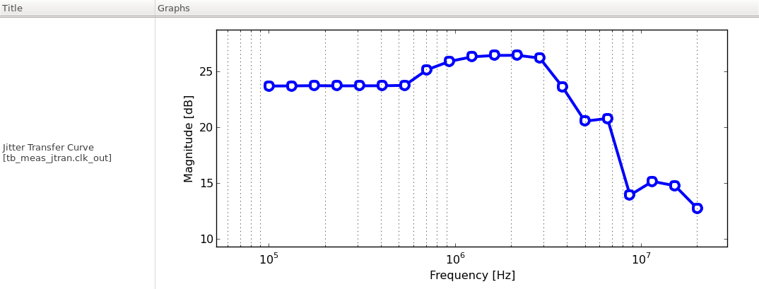
Figure. jitter transfer function of the PLL.
tb_meas_phasestep : A testbench for measuring the phase step response of a PLL
This testbench measures the response of a PLL to a step change in its input clock phase. Once the PLL acquires a lock, the testbench applies a step change in its input clock phase using the step_gen and phase_to_clk primitives. The responses in the output clock frequency and phase indicate the loop bandwidth and stability of the PLL.
`include "xmodel.h"

module tb_meas_phasestep();

    parameter real ref_freq = 312.5e6;  // reference frequency
    parameter real phase_step = 1.0;    // phase step amount
    parameter real delay = 1.5e-6;      // A point to make phase step

    // variables
    `xbit(clk_ref);                     // reference clock
    `xbit(clk_out);                     // output clock
    bit reset;

    // phase step generator
    `xreal(phase);
    step_gen     #(.init_value(0.0), .change(phase_step), .delay(delay))
                 step_gen(phase);

    // reference clock generator
    phase_to_clk #(.freq(ref_freq)) clk_ref_gen(.in(phase), .out(clk_ref));

    //reset
    initial begin
        reset = 1;
        #(20e-9/`TIME_SCALE) reset = 0;
    end

    // DUT (device-under-test) digital PLL
    PLL_DigitalPLL  DUT (.in(clk_ref), .out(clk_out), .reset(reset));

    // probing
    probe_xbit  probe_ref(clk_ref);
    probe_xbit  probe_out(clk_out);
    probe_freq  probe_freq(clk_out);
    probe_phase #(.freq(16*ref_freq), .phase_wrap(0)) probe_fb_phase(clk_out);
    probe_phase #(.freq(ref_freq), .phase_wrap(0)) probe_ref_phase(clk_ref);

endmodule
Simulation Results
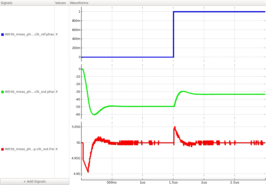
Figure. phase step response of the PLL.