OSC_LinearVCO8O : A voltage-controlled oscillator (VCO) with a linear V-to-f characteristic and 8 outputs
A voltage-controlled oscillator (VCO) generates one or more clock signals out of which frequency varies with the control input in. In particular, this VCO model describes a VCO of which frequency varies linearly with the input in, as described by the following equation:
frequency = freq0 + Kvco * (in - in0)
The parameter freq0 sets the nominal frequency of the VCO when the input is at its nominal value set by the parameter in0. And the parameter Kvco defines the VCO gain, defining the rate of change in the VCO frequency with respect to the input.
This VCO model is described using a poly_func primitive followed by a freq_to_clk primitive. The poly_func primitive calculates the frequency value from the input in and the freq_to_clk primitive produces clocks with the corresponding frequency. The phase noise characteristics of the VCO can be modeled by defining the phase noise parameters of the freq_to_clk primitive, such as PN_fcenter, PN_foffset, PN_dbc, PN_fcorner, and PN_floor. For more information on these parameters, please refer to the documentation on the freq_to_clk primitive.
Input/Output Terminals
| Name | I/O | Type | Description |
| out[7:0] | output | xbit | output clock |
| in | input | xreal | input voltage |
Parameters
| Name | Type | Default | Description |
| in0 | real | 0.5 | nominal input value (V) |
| freq0 | real | 16G | VCO frequency at nominal input value (Hz) |
| Kvco | real | 1G | VCO gain (Hz/V) |
| PN_fcenter | real | -1.0 | phase noise center frequency (Hz) |
| PN_foffset | real | 0.0 | phase noise offset frequency (Hz) |
| PN_dbc | real | -`INFINITY | phase noise measured in dBc/Hz (dBc/Hz) |
| PN_fcorner | real | 0.0 | 1/f^3 phase noise corener frequency (Hz) |
| PN_floor | real | -`INFINITY | phase noise floor measured in dBc/Hz (dBc/Hz) |
| RJ_kappa | real | 0.0 | RMS accumulated random jitter after 1 second (second) |
| RJ_rms | real | 0.0 | RMS independent random jitter (second) |
List of Testbenches
| tb_meas_tfdc : A testbench for measuring the voltage-to-frequency characteristic of a VCO |
tb_meas_tfdc : A testbench for measuring the voltage-to-frequency characteristic of a VCO
This testbench measures the voltage-to-frequency (V-to-f) characteristic of a voltage-controlled oscillator (VCO) by applying a gradually-varying voltage to the VCO input and measuring its output frequency.
The measured frequency is expected to change with the input voltage according the V-to-f equation assumed by the VCO model.
`include "xmodel.h"

module tb_meas_tfdc();

    xreal vctrl;            // input voltage
    xbit [7:0] out;         // output clock
    xbit out0;              // alias for out[0]

    // stimuli
    pwl_gen #(.data('{100e-9, 0.1, 900e-9, 0.9}))
            vctrl_gen(vctrl);

    // DUT (device-under-test)
    OSC_LinearVCO8O     DUT(.in(vctrl), .out(out));

    // measurements
    assign out0 = out[0];
    probe_xreal probe_vctrl(vctrl);
    probe_freq  probe_out(out0);

endmodule
Simulation Results
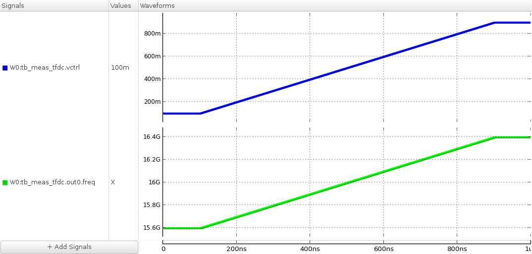
Figure. the V-to-f characteristic of the VCO.