Languages
In my company, when extracting models using GLISTER or MODELZEN, we found it convenient to define the input ports receiving DC bias voltages as 'bit' types and define their bias voltage values as their logic-1 levels. This way, it becomes easy to compose a top-level testbench that just "enables" these bias input ports with a digital 1 value without having to keep track of the correct bias voltage values across the design hierarchies. In other words, when the bias input port declared as bit type receives a logic-1 value, the bit_to_xreal primitive auto-inserted by GLISTER or MODELZEN within the model would translate it to a pre-defined bias voltage required for the rest of the circuits.
One problem of this approach is, however, that some of the bias input ports receive currents instead of voltages. Is there a way to specify the conversion levels for the port so that the digital values received by the bit-type input ports would be translated to pre-defined bias currents?
That's a clever way of building models! Starting with the 2019.04 release, GLISTER and MODELZEN let you define the conversion levels with current values for bit- and xbit- type input ports. Simply put, you can use an 'i:' prefix to do so.
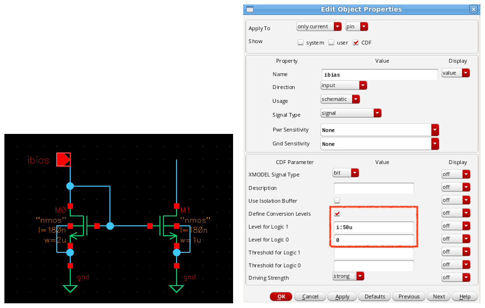
Here is a simple example for illustration. Let's assume that the circuit shown below expects a DC bias current of 50uA entering into a port named 'ibias'. To declare this port as a bit-type port and define its conversion levels, select its pin symbol and click the Properties menu to open the Edit Object Properties dialog window as shown below. From that dialog window, set the XMODEL signal type as 'bit' and check the Define Conversion Levels field to display the fields for the conversion level information. If you'd like the logic-1 value received by this port to be translated to a 50uA current entering into the port, define the Level for Logic 1 field with i:50u. If you'd like the logic-0 value to be translated to a zero current, define the Level for Logic 0 field with 0.
As you can see, the 'i:' prefix indicates that the value you are specifying is for a current. It is also possible to use a scale suffix such as 'u' for 1e-6, 'm' for 1e-3, and 'n' for 1e-9. Note that a current may either flow into the port or flow out of the port. Our convention is that the current flowing along with the port direction has a positive polarity while the current flowing against the port direction has a negative polarity. For example, if you want a 100uA current flowing out of the input port, you can specify its conversion level as i:-100u.
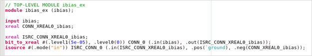
Here is an excerpt of the model generated from this circuit example by MODELZEN. The port 'ibias' is defined as bit type (wire type, actually) and the bit_to_xreal and isource primitives convert it into a current with the value specified by the conversion levels.
Please note that the use of current-valued conversion levels is supported only for ports converting a bit or xbit-type value to an xreal-type value.
Please login or Register to submit your answer
저희 회사에서는 GLISTER나 MODELZEN을 사용해 모델을 추출할때, DC 바이어스 전압을 입력받는 포트들을 bit 타입으로 선언하고, 회로 동작에 필요한 바이어스 전압값을 그 포트의 로직-1 변환레벨값으로 정의하는 방식을 씁니다. 이렇게 했을 때의 장점은, 상위 수준에서의 모델 또는 테스트벤치를 구성할때, 하위 블록들이 필요로 하는 바이어스 전압값을 일일이 기억할 필요없이, 그저 디지털 1값으로 활성화(enable)만 해주면 된다는 것입니다. 다시 말해, 이렇게 bit 타입으로 선언된 바이어스 입력포트에 디지털 1값을 인가해주면, 그 값은 GLISTER 또는 MODELZEN이 모델 안에 자동삽입한 bit_to_xreal primitive에 의해 미리 로직-1 변환레벨값으로 정의해둔 바이어스 전압값으로 변환되고, 그 바이어스 전압이 모델내의 다른 회로들에 공급되게 됩니다.
다만, 이 방식의 한가지 문제점은, 어떤 바이어스 입력포트들은 전압 대신 전류를 입력으로 받는다는 것입니다. 해당 포트의 변환레벨값을 정의하여, bit 타입 입력포트가 받은 디지털 값 정보가 미리 정의된 바이어스 전류값으로 변환되도록 하는 방법이 있을까요?
That's a clever way of building models! Starting with the 2019.04 release, GLISTER and MODELZEN let you define the conversion levels with current values for bit- and xbit- type input ports. Simply put, you can use an 'i:' prefix to do so.
Here is a simple example for illustration. Let's assume that the circuit shown below expects a DC bias current of 50uA entering into a port named 'ibias'. To declare this port as a bit-type port and define its conversion levels, select its pin symbol and click the Properties menu to open the Edit Object Properties dialog window as shown below. From that dialog window, set the XMODEL signal type as 'bit' and check the Define Conversion Levels field to display the fields for the conversion level information. If you'd like the logic-1 value received by this port to be translated to a 50uA current entering into the port, define the Level for Logic 1 field with i:50u. If you'd like the logic-0 value to be translated to a zero current, define the Level for Logic 0 field with 0.
As you can see, the 'i:' prefix indicates that the value you are specifying is for a current. It is also possible to use a scale suffix such as 'u' for 1e-6, 'm' for 1e-3, and 'n' for 1e-9. Note that a current may either flow into the port or flow out of the port. Our convention is that the current flowing along with the port direction has a positive polarity while the current flowing against the port direction has a negative polarity. For example, if you want a 100uA current flowing out of the input port, you can specify its conversion level as i:-100u.
Here is an excerpt of the model generated from this circuit example by MODELZEN. The port 'ibias' is defined as bit type (wire type, actually) and the bit_to_xreal and isource primitives convert it into a current with the value specified by the conversion levels.
Please note that the use of current-valued conversion levels is supported only for ports converting a bit or xbit-type value to an xreal-type value.
Please login or Register to submit your answer