Using MODELZEN with GLISTER
By using MODELZEN via the GLISTER interface integrated into Cadence® Virtuoso® Schematic Editor, you can generate XMODEL/SystemVerilog models directly from the circuit schematics just with a single mouse button click and set MODELZEN properties for individual pins and devices using an intuitive graphical user interface. This Section explains the GLISTER interface for using MODELZEN in Cadence® Virtuoso® and provides instructions on how to setup some necessary configurations.
Running MODELZEN with GLISTER
A quick way to try out the GLISTER interface for MODELZEN is to follow the tutorial included in the XMODEL installation package. The tutorial is located in ${XMODEL_HOME}/tutorial/modelzen_basic where ${XMODEL_HOME} is the XMODEL installation directory. For instance, you can launch the Cadence® Virtuoso® session try out the example explained in this Section by executing these lines:
$ cp -R ${XMODEL_HOME}/tutorial/modelzen_basic ~/modelzen_basic
$ cd ~/modelzen_basic

$ source etc/setup.bashrc  # for bash-like shells
$ source etc/setup.cshrc   # for csh-like shells

$ cd cadence
$ virtuoso &
The more detailed instructions on how to follow the tutorial are provided in the ${XMODEL_HOME}/tutorial/modelzen_basic/doc directory. The tutorial”s default setup assumes that the Cadence® Virtuoso® Schematic Editor and Synopsys® HSPICE simulator are properly configured. Please refer to their corresponding documentations or consult your site administrators if they are already done so.
The basic way of generating the XMODEL/SystemVerilog model form a circuit schematic is to select the GLISTER->Run MODELZEN on the pull-down menu bar or simply click the icon  from the menu toolbar.
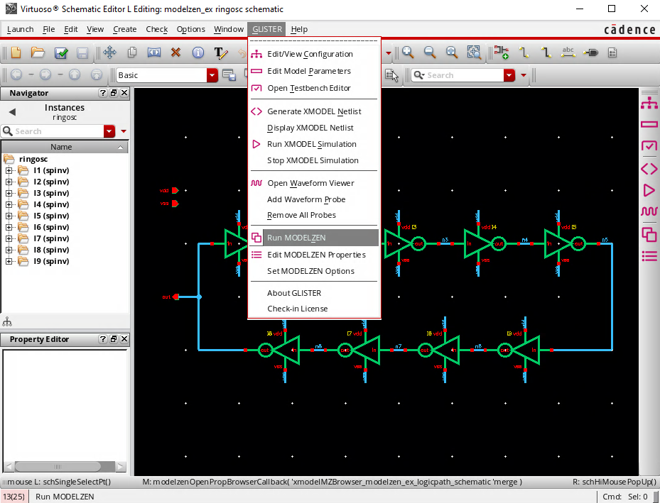
Figure 15. Running MODELZEN using the GLISTER interface in Cadence® Virtuoso® Schematic Editor.
When you select the GLISTER->Run MODELZEN menu or click the icon  , GLISTER performs the following steps:
- Extract circuit netlists (e.g. SPICE netlists) from the schematic cellview.
- Extract MODELZEN properties from the schematic cellview.
- Run MODELZEN to generate XMODEL/SystemVerilog models from the circuit netlists.
- Import the generated model into the design database as xmodel view.
Figure 16 is the MODELZEN progress dialog displayed while these steps are being performed.
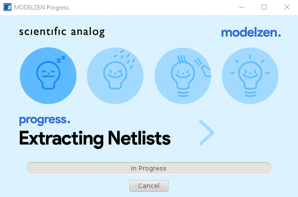
Figure 16. The MODELZEN progress dialog window.
Depending on the MODELZEN option values, GLISTER may pop-up the MODELZEN GUI window during the model generation process as shown in Figure 17. Note that the input filename and design information filename are filled with the filenames generated by GLISTER. The more description on circuit netlist and design information file generation will be given in the later part of this Section. The MODELZEN GUI window is also pre-loaded with the option values defined in the technology configuration file. If all the option values on the MODELZEN GUI window are what you desire, you can proceed with the model generation by clicking the OK button.
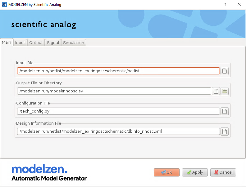
Figure 17. The MODELZEN GUI window with the input filename and design information filename filled by GLISTER.
When you select the GLISTER->Set MODELZEN Options from the Cadence® Virtuoso® Schematic Editor pull-down menu bar, the dialog box shown in Figure 18 will pop-up, allowing you to control the ways MODELZEN is run by GLISTER. For instance, the Netlist Simulator field sets the format of the circuit netlist to be extracted from the schematic cellview and the Technology Configuration File field sets the default technology configuration file to be used by MODELZEN. Table 13 lists the MODELZEN-related GLISTER options and their descriptions.
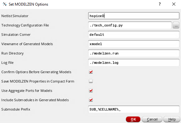
Figure 18. The dialog box for setting MODELZEN options.
Table 13. Listing of MODELZEN-related GLISTER options and their descriptions.
| Option Name | Description |
| Netlist Simulator | Cadence® netlist simulator name, determining the format of the circuit netlist extracted from the schematic cellview (e.g. hspiceD, spectre, cdl, etc.). |
| Technology Configuration File | The path of the technology configuration file used by MODELZEN. |
| Simulation Corner | The name of the simulation corner that defines a set of process or temperature conditions for the devices being characterized. |
| Viewname of Generated Models | The view name of the xmodel-type cellview importing the generated structural model file. |
| Run Directory | The directory under which the MODELZEN run-time files are stored, such as the circuit netlists, simulation data, and generated models. |
| Log File | The name of the MODELZEN log file. As part of the filename, you can use special fields such as %LIBNAME%, %CELLNAME%, and %VIEWNAME% to generate different log files for each cellview processed. |
| Confirm Options Before Generating Models | A flag whether to pop-up the MODELZEN GUI window for user’s confirmation before proceeding with model generation. |
| Save MODELZEN Properties in Compact Form | A flag whether to save MODELZEN properties in compact form to reduce the file size. Effective only for the FileàSave File menu action of the MODELZEN Property Browser. |
| Use Aggregate Ports for Models | If this flag is checked, MODELZEN does its best to preserve the ports and their orderings defined in the schematic cellview, including bus-type ports (e.g. A<3:0>) and aggregate ports (e.g. “A,B”). Otherwise, aggregate ports (e.g. “A,B”) will be separated into individual ports (e.g. “A” and “B”). |
| Include Submodules in Generated Models | A flag whether to include all the submodule descriptions used by the current design cellview in the generated XMODEL/SystemVerilog model. If this flag is unchecked, the model includes only the description for the current top-level cell. |
| Submodule Prefix | An optional prefix to be prepended to the submodule names to avoid name collisions with the submodule names used by other cells’ models. The prefix string may contain special fields such as %LIBNAME%, %CELLNAME%, and %VIEWNAME%, which will be replaced with the library, cell, and view names of the design cellview, respectively. |
Cadence® Virtuoso® Setup for MODELZEN
If you wish to use MODELZEN via GLISTER, you may need to perform some setups in addition to the basic setups required for XMODEL and GLISTER explained in the XMODEL Installation Guide or XMODEL Setup Summary documentations:
- Override MODELZEN-related GLISTER default options if necessary
- Configure how MODELZEN extracts circuit netlists from schematic cellviews (
modelzenGenNetlist())
Overriding MODELZEN-related GLISTER Default Options
It is possible to override the default values of the MODELZEN- related GLISTER options listed in Table 13. Each of the options shown in the Set MODELZEN Options dialog in Figure 18 has a corresponding SKILL variable which holds its default value when GLISTER is initialized. Therefore, overriding any of these values after loading the XMODEL context file has the effects of changing the default values.
An excerpt of the Cadence® Virtuoso® initialization file .cdsinit that overrides some of the MODELZEN-related GLISTER options is listed below. The first part initializes the XMODEL/GLISTER interface for Cadence® Virtuoso® as explained in the XMODEL Installation Guide. The second part redefines some SKILL variables with a prefix “modelzen” to override the default values of the MODELZEN-related GLISTER options.
; XMODEL/Virtuoso Integration Setup
printf( "Loading XMODEL/Virtuoso Integration...\n" )
XMODEL_HOME = getShellEnvVar("XMODEL_HOME")
loadContext( strcat( XMODEL_HOME "/cadence/etc/xmodel.cxt" ) )
callInitProc( "xmodel" )

; MODELZEN options (NOTE: must come after context file loading)
modelzenDefaultModelView = "xmodel"
modelzenDefaultConfigFile = "./tech_config.py"
modelzenDefaultRunDir = "./modelzen.run"
modelzenDefaultNetlistSimulator = "hspiceD"
modelzenSubModulePrefix = "SUB_%CELLNAME%_"
modelzenShowOptionDialog = t
Table 14 lists the names of the SKILL variables that define the default values of the MODELZEN-related GLISTER options listed in Table 13.
Table 14. Listing of the SKILL variables setting the default values of the MODELZEN- related GLISTER options.
| Option Name | Corresponding SKILL Variable Name |
| Netlist Simulator | modelzenDefaultNetlistSimulator |
| Technology Configuration File | modelzenDefaultConfigFile |
| Simulation Corner | modelzenDefaultCorner |
| Viewname of Generated Models | modelzenDefaultModelView |
| Run Directory | modelzenDefaultRunDir |
| Log File | modelzenDefaultLogFile |
| Confirm Options Before Generating Models | Set modelzenShowOptionDialog as t to select this flag |
| Save MODELZEN Properties in Compact Form | Set modelzenIncludeAllPinInfo as nil to select this flag |
| Use Aggregate Ports for Models | Set modelzenUseAggregatePorts as t to select this flag. |
| Include Submodules in Generated Models | Set modelzenSubModulePrefix with any stringto select this flag; setting it as nil unselects this flag. |
| Submodule Prefix | modelzenSubModulePrefix |
Note that unchecking the Confirm Options Before Generating Models in the Set MODELZEN Options dialog, or equivalently, setting modelzenShowOptionDialog variable to nil realizes a truly single- click flow for automatic model generation.
modelzenShowOptionDialog = nil
Configure How MODELZEN Extracts Circuit Netlists from Schematic Cellviews
Running MODELZEN from Cadence® Virtuoso® Schematic Editor using the GLISTER interface involves extracting a circuit netlist from the schematic cellview. If your design environment uses a customized procedure or interface for extracting SPICE or Spectre netlists from the schematic cellview, you may need to redefine a SKILL procedure named modelzenGenNetlist() in order for MODELZEN to use the same steps when extracting the circuit netlists.
The usage format of the SKILL function modelzenGenNetlist() is shown as below:
modelzenGenNetlist( libName cellName viewName simulator )
The function takes four arguments libName, cellName, viewName, and simulator where libName, cellName, and viewName are the library, cell, and view names of the design cellview to be netlisted and simulator is the name of the Cadence® netlist simulator that determines the format of the netlist (e.g. hspiceD, spectre, and cdl). The function then extracts a netlist from the cellview and returns the full path to the extracted netlist file.
To redefine the modelzenGenNetlist() function, one may need to know the basics of SKILL programming and specific steps required for netlisting in her or his design environment. Please refer to the appropriate Cadence® documentations, or consult your PDK providers or CAD administrators in case you need further help.
The following codes show the default modelzenGenNetlist() function which is defined when the XMODEL/GLISTER context file is first loaded. It extracts the netlist using the Cadence® Analog Design Environment (ADE) SKILL functions such as simulator(), design(), and createNetlist(). If you can extract netlists from your schematic cellview via the standard ADE interface, it is likely that you do not need to redefine modelzenGenNetlist().
; modelzenGenNetlist( libName cellName viewName simulator ):
; generates the 'simulator' netlist of a cellview and
; returns the full filepath of the generated netlist
procedure( modelzenGenNetlist( libName cellName viewName simulator )
    let( ( netlistFile netlistDir )
        ; initialize simulator
        simulator( simulator )

        ; generate netlist
        design( libName cellName viewName )
        unless( netlistFile = createNetlist( ?recreateAll t ?display nil )
           error( "error occurred while netlisting %s.%s:%s."
                  libName cellName viewName )
        )
        ocnCloseSession()

        ; return netlist filename
        netlistDir = xmodelGetDirName( netlistFile )
        strcat( netlistDir "/netlist" )
    )
)
Using MODELZEN Properties
When generating models from circuit netlists, MODELZEN converts each device element contained in the circuit netlist to an equivalent XMODEL primitive. The device-to-primitive mapping and model fitting options are defined in the technology configuration file as previously explained in Section 4.
Sometimes, it may be necessary to locally override the global mapping or options defined in the technology configuration file for selected instances or pins. For instance, one may wish to use different level_dc or level_ac options for some particular transistors for improved accuracy or speed. Also, one may wish to specify additional properties on some pins to extract their ports as wire-type rather than as xreal-type. These additional options or properties defined for specific instances or pins to override the global the technology configuration file are called MODELZEN properties.
GLISTER allows users to set these MODELZEN properties on the instances or pins on the schematic cellview leveraging the graphical user interface of the Cadence® Virtuoso® Schematic Editor. You can also use the MODELZEN Property Browser to browse all the MODELZEN properties defined for the current schematic cellview as well as those for its sub-instances.
During the model generation process, GLISTER extracts the MODELZEN properties defined in the design database and exports them to a design information file in XML format. This design information file is then passed to MODELZEN using the Design Information File in the Main tab of the GUI dialog window or using the --dbinfo option on the command line. MODELZEN then reflects the MODELZEN properties contained in this design information file to its model generation process.
Editing Instance-Specific MODELZEN Properties
To edit MODELZEN properties of a device instance, select the instance, open the pop-up menu by clicking the right mouse button, and select the MODELZEN Properties item, as shown in Figure 19. Alternatively, you can select the Edit->Properties->MODELZEN pull- down menu item of the Cadence® Virtuoso® Schematic Editor. Unless overridden otherwise, you can also press Ctrl+Q key as a short cut.
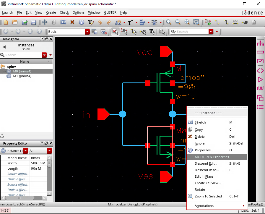
Figure 19. Pop-up menu for editing instance-specific MODELZEN properties.
Then, a dialog window such as the one in Figure 20 will open. You can select the model type (i.e., the XMODEL primitive to map this instance to), the levels for DC and AC modeling (i.e., the level_dc and level_ac options, respectively), and the maximum and minimum voltages for the device (i.e. vmax and vmin, respectively). Also, define the port mapping between the device instance and XMODEL primitive especially when the two have different numbers of ports or different names.
You can clear the MODELZEN properties defined for the instance by clicking the Defaults button located on the bottom of the dialog window. In this case, the device instance will be characterized according to the options defined in the global technology configuration file.
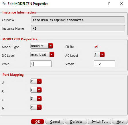
Figure 20. Dialog window for editing instance-specific MODELZEN properties.
Editing Pin-Specific MODELZEN Properties
You can also define MODELZEN properties for pins of the schematic cellview. For instance, you can define a particular port of the model as other data types than xreal or insert an isolation buffer to force cluster partitioning.
To edit MODELZEN properties of a pin, select the pin symbol on the schematic, open the pop-up menu by clicking the right mouse button, and select the MODELZEN Properties item, as shown in Figure 21. Alternatively, you can select the Edit->Properties->MODELZEN pull-down menu item of the Cadence® Virtuoso® Schematic Editor. Unless overridden otherwise, you can also press Ctrl+Q key as a short cut.
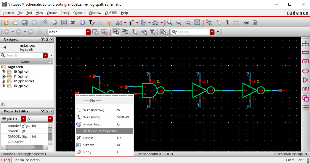
Figure 21. Pop-up menu for editing pin-specific MODELZEN properties.
Then, a dialog window such as the one in Figure 22 will open. You can select the XMODEL signal type (xreal, real, bit, or xbit), decide whether to insert an isolation buffer at this port, or define the conversion levels in case the signal is converting between analog and digital data types. Note that the bit type denotes the 4- value logic type in Verilog, which is equivalent to the wire, reg, or logic types.
You can clear the MODELZEN properties defined for the pin by clicking the Defaults button located on the bottom of the dialog window.
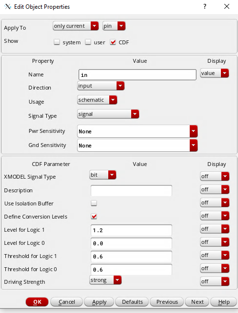
Figure 22. Dialog window for editing pin-specific MODELZEN properties.
Using MODELZEN Property Browser
One difficulty in working with MODELZEN properties is that they are not visible on the schematic after defining them. The MODELZEN Property Browser provides a convenient interface to browse the MODELZEN properties defined on all the pins and instances of the current cellview as well as its dependent cellviews all at once.
To open the MODELZEN Property Browser, select the GLISTER->Edit MODELZEN Properties item from the pull-down menu or click the icon  on the menu toolbar. The locations of these menu and icon are highlighted in Figure 23.
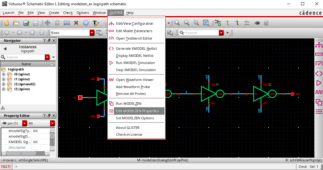
Figure 23. The GLISTER pull-down menu and toolbar icon for opening the MODELZEN Property Browser.
Figure 24 and Figure 25 show the MODELZEN Property Browser dialog windows. You can browse either the pin-specific MODELZEN properties or instance-specific MODELZEN properties listed in a table format by selecting the corresponding tabs in the window. Also, you can sort the items in the table by any fields by clicking the corresponding buttons located at the top of the table.
If the Show All Dependent Cells option is selected, the MODELZEN Property Browser displays the MODELZEN properties of the current cellview as well as its dependent cellviews in the table. It is a convenient way to browse the MODELZEN properties defined in the entire design hierarchy.
Also, you can edit the MODELZEN properties of any pin or instance directly from this MODELZEN Property Browser either by double- clicking the item or invoking the Edit->Edit Selected menu once the item is selected.
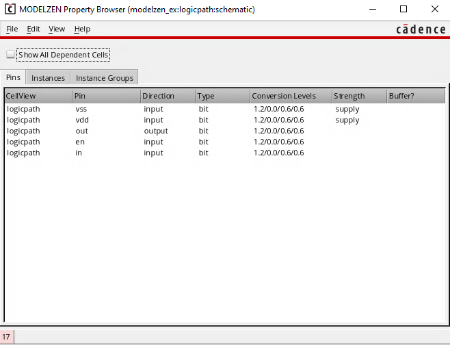
Figure 24. The MODELZEN Property Browser displaying pin-specific MODELZEN properties in the current design cellview.
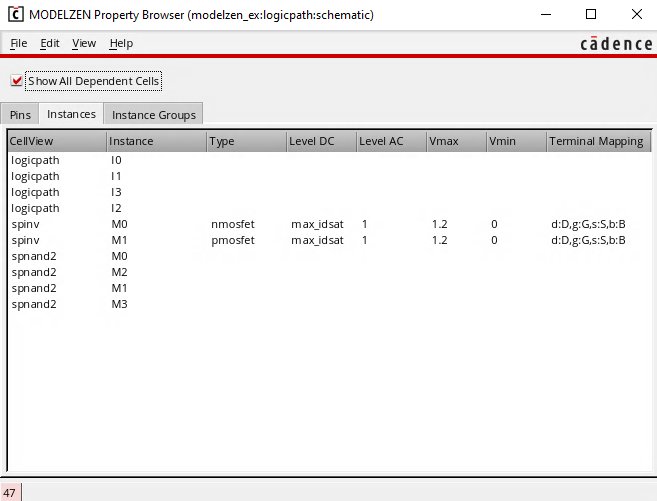
Figure 25. The MODELZEN Property Browser displaying instance-specific MODELZEN properties in the current design cellview as well as in its dependent cellviews.
Exporting/Importing MODELZEN Properties
It may be necessary to export the MODELZEN properties defined for the design to a file and import the MODELZEN properties back to the design. One scenario is that you are only allowed to work on a copy of the design database while the main database is still being updated. In this case, when the design database is updated and you need to make a new copy, you can export the MODELZEN properties from the old database and import them to the new database.
The MODELZEN Property Browser provides ways to export and import the MODELZEN properties of a design cellview. As shown in Figure 26, you can load or merge the MODELZEN properties defined in a file or save the MODELZEN properties defined in the cellview and its dependents to a file by selecting the corresponding items in the MODELZEN Property Browser”s File menu.
Note that the difference between loading and merging is that loading clears all the MODELZEN properties already defined for that cellview while merging does not.
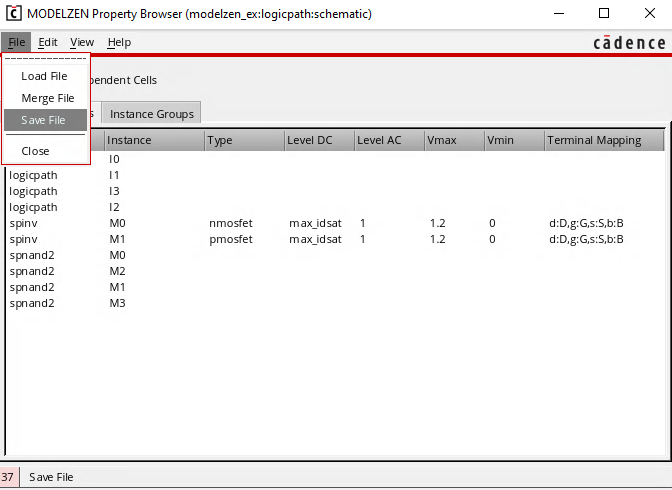
Figure 26. The MODELZEN Property Browser”s File menu to load, merge, and save a design information file.
The file that stores the MODELZEN properties for the purpose of exporting and importing MODELZEN properties in and out of the design cellview has the similar XML format to the design information file used for model generation and discussed earlier. However, there may be some minor differences between the two formats and it is advised not to use the file generated for one purpose for the other.
Especially, by setting the Save MODELZEN Properties in Compact Form option, one can reduce the file size by excluding the pin and instance information already present in the design from the export file. In this case, the file does not have sufficient information to be used as design information file.