MODELZEN Run-Time Options
MODELZEN provides a set of run-time options to support diverse user scenarios. To see what options are available, you can type:
modelzen -h
Or, type:
modelzen --gui
and browse the options available on the Input, Output, Signal, and Simulation tabs on the GUI window.
The following set of tables provides more detailed explanation on each option available in MODELZEN.
Main Input/Output Options
The following options define the input and output file/directories as well as technology configuration and design information files required for model generation.
Table 1. Listing of main input/output options.
| Option | Description |
FILENAME |
Filename of the input circuit netlists either in SPICE, CDL, or Spectre format. It is a positional argument. |
-o FILENAME, |
Filename of the SystemVerilog model to be generated. If this option is specified, all the top-level and sub-level modules will be listed in the same file. |
-d DIRPATH, |
Path of the directory to store the generated model files. If this option is specified, each of the top-level and sub-level modules will be listed in separate, individual files. |
-c FILENAME |
Filename of the technology configuration file. The file defines the technology-specific information such as SPICE command and model library locations. If not specified, the default options defined in the $XMODEL_CONFIG file or $XMODEL_HOME/etc/default_config.py will be used. |
--dbinfo FILENAME |
Filename of the XML-format design information file. The file contains instance- or pin-specific options to direct model generation. Typically, this file is generated from circuit schematics by GLISTER. |
--gui |
Invoke graphical user interface (GUI). |
-h, --help |
Show help messages. |
Many of these options correspond to the ones found in the Main tab of the MODELZEN GUI window shown in Figure 7.
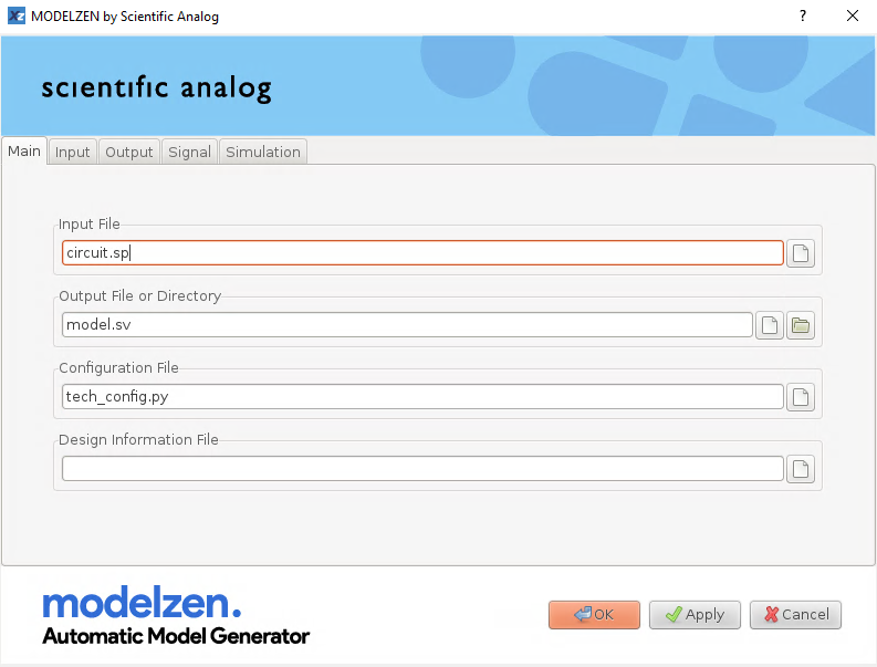
Figure 7. The MODELZEN options in the Main tab.
Input Netlist Parsing Options
When reading input circuit netlists, MODELZEN can perform additional processing on the netlist to avoid commonly- encountered pitfalls. Many of these pitfalls are due to the format differences between SPICE and Verilog. For instance, since SPICE netlists are case-insensitive, they may have all the letters in upper cases while users may want them in lower cases in the generated models. Also, while SPICE-format netlists expand all bus-type signals to a list of elements, users may want them to be merged back to the original bus format.
Table 2. Listing of options related to input netlist parsing.
| Option | Description |
-f FORMAT, |
Input netlist format. It can be either "spice", "cdl", or "spectre". |
-u, --upper |
Convert all letters in the netlist to uppercase before parsing. |
-l, --lower |
Convert all letters in the netlist to lowercase before parsing. |
-m FORMAT, |
Merge the expanded lists of element signals to buses. For instance, a list of a[2], a[1], and a[0] will be merged to a[2:0]. FORMAT specifies whether to use big-endian indexing ("big_endian") or little-endian indexing ("little_endian") in the merged buses. |
-e MODULENAME, |
Expand (i.e. flatten) the named subcircuit modules during the topology analysis. This option is useful especially when flattening a certain subcircuit instance can enable significant model reduction. |
-p NAME=VALUE, |
Define global parameter values used in the subcircuit or instance parameter expressions. This option is useful when the input netlist depends on some global parameter values not defined in the netlist itself (e.g. scale factors). |
These options correspond to the ones found in the Input tab of the MODELZEN GUI window shown in Figure 8.
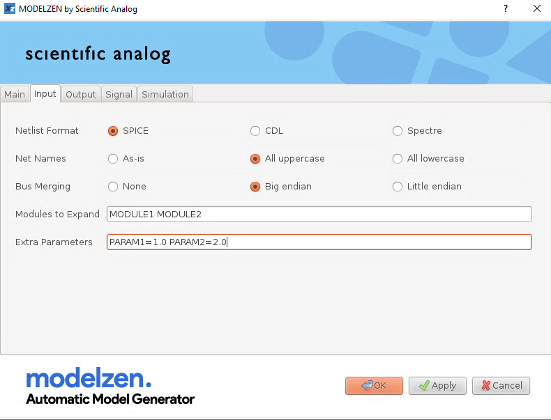
Figure 8. The MODELZEN options in the Input tab.
Topology Analysis and Processing Options
MODELZEN can perform topology simplification after analyzing the circuit topology. It helps reducing the complexity of the generated model and enhancing the simulation speed, with minimal impact on the simulation accuracy. The following options individually control whether to perform various topology simplification strategies supported by MODELZEN. Each of these options requires a CONDITION field. When multiple CONDITION fields should be specified, one can use multiple instances of the same options.
For instance, to enable both parallel device merging and serial device merging, use:
modelzen ... --enable-merge parallel --enable-merge serial
And, to trim any shunt resistance of which resistance is larger than 1G-ohms, use:
modelzen ... --enable-trim "R>1e9"
Table 3. Listing of options related to topology analysis and parsing.
| Option | Description |
--enable-merge CONDITION |
Enable device merging. CONDITION can be "parallel" or "serial". |
--disable-merge CONDITION |
Disable device merging. CONDITION can be "parallel" or "serial". |
--enable-reduce CONDITION |
Enable opportunistic device reduction. CONDITION can be "nmosfet->capacitor", "pmosfet->capacitor", "nmosfet->diode", or "pmosfet->diode". If this option is enabled, MODELZEN reduces transistors with source and drain nodes shorted to capacitors and transistors with gate and drain nodes shorted to diodes, respectively. |
--disable-reduce CONDITION |
Disable opportunistic device reduction. CONDITION can be "nmosfet->capacitor", "pmosfet->capacitor", "nmosfet->diode", or "pmosfet->diode". |
--enable-trim CONDITION |
Enable trimming of negligible devices, such as series resistors with too low resistance and shunt resistors with too high resistance. CONDITION can be "R>VALUE", "R<VALUE", "C>VALUE", "C<VALUE", "L>VALUE", or "L<VALUE", where VALUE is the numerical value setting the maximum or minimum threshold on the element values to be trimmed. |
--disable-trim CONDITION |
Disable trimming of negligible devices, such as series resistors with too low resistance and shunt resistors with too high resistance. CONDITION can be "R>VALUE", "R<VALUE", "C>VALUE", "C<VALUE", "L>VALUE", or "L<VALUE", where VALUE is the numerical value of the threshold. |
Output Model Generation Options
MODELZEN can perform additional processing during the generation of models. For instance, it can prepend prefix string to each sub-level module name or insert power supplies inside the module. The following table explains these options.
Table 4. Listing of options related to output model generation.
| Option | Description |
--top MODULENAME, |
Name of the top-level module. Some circuit netlists contain top-level circuits without an enclosing subcircuit definition. In that case, this option can set the name of the corresponding top-level module. Default is '__TOP__'. |
-g MODULENAME, |
Name of the module containing the global signal definitions. Since SystemVerilog does not support global signals, all the global signals used in the circuit netlist are defined inside this module and referenced by other modules using the full hierarchical name (e.g. "GLOBAL.vdd"). Default is "GLOBAL". |
--mod-prefix PREFIX |
Prepend PREFIX to the names of all sub-level modules. Note that the name of the top-level module name is set by the -topmodule option and will not be affected by this option. |
--ignore-pindir |
Ignore the pin directions defined for the sub-level modules and generate all of their ports as input's. |
--no-portmacros |
By default, MODELZEN defines the module ports using macros, for example, input_xreal and output_xreal. If this option is specified, MODELZEN defines the ports without using these macros: e.g., input xreal and output xreal. |
-s NAME=VALUE, |
Indicating the named signal is a supply with the specified value. If this option is specified, MODELZEN inserts a dc voltage source inside the module containing the named signal and removes the signal from the terminal list. |
The --ignore-pindir option may deserve further explanation. When MODELZEN is used from Cadence® Virtuoso®, it annotates the port direction information from the circuit schematics via the design information file. However, since SPICE does not have a notion of port direction while Verilog does, it is possible that the user's circuit schematics may contain input/output port connections which are illegal in Verilog, e.g. multiple output ports driving the same node. In this case, one simple remedy is to treat all the ports of the sub-level modules as "inputs" so that there would be no illegal connections. This does not affect the simulation behavior, since the XMODEL simulation engine considers all the connections among the XMODEL circuit-level primitives as bi-directional regardless of their apparent port directions.
The options listed in Table 4 correspond to the ones found in the Output tab of the MODELZEN GUI window shown in Figure 9.
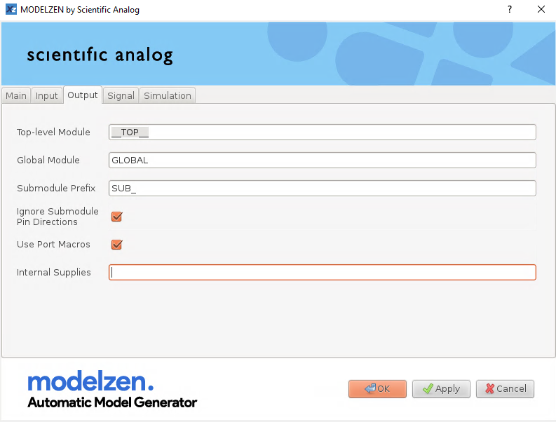
Figure 9. The MODELZEN options in the Output tab.
Signal Type Conversion Options
By default, MODELZEN extracts all signals as xreal types. However, sometimes there is a need to extract certain input/output ports as wire types or xbit types, especially when the generated models interface with digital modules (i.e., pure Verilog modules) directly. MODELZEN can insert connector modules at the module interface boundary to do this conversion. The following options define the conversion levels and threshold levels for this conversion.
The --wire and --xbit options turn all the I/O signals of the specified module into wire or xbit typed signals, respectively. Currently, the most recommended way of controlling this behavior is to define the MODELZEN properties of the pin instances in the circuit schematics, as explained in Section 5.
Table 5. Listing of options related to signal type conversion.
| Option | Description |
--level1 VALUE |
Global conversion level for logic 1. |
--level0 VALUE |
Global conversion level for logic 0. |
--thres1 VALUE |
Global threshold level for logic 1. |
--thres0 VALUE |
Global threshold level for logic 0. |
--strength VALUE |
Global strength level for logic driver (VALUE: 0~7). |
--wire MODULENAME=SUPPLY |
Make all the I/O ports of the named module wire-typed assuming the specified supply level (e.g. -wire xyz=1.2). |
--xbit MODULENAME=SUPPLY |
Make all the I/O ports of the named module xbit-typed assuming the specified supply level (e.g. -xbit xyz=1.2). |
These options correspond to the ones found in the Signal tab of the MODELZEN GUI window shown in Figure 10.
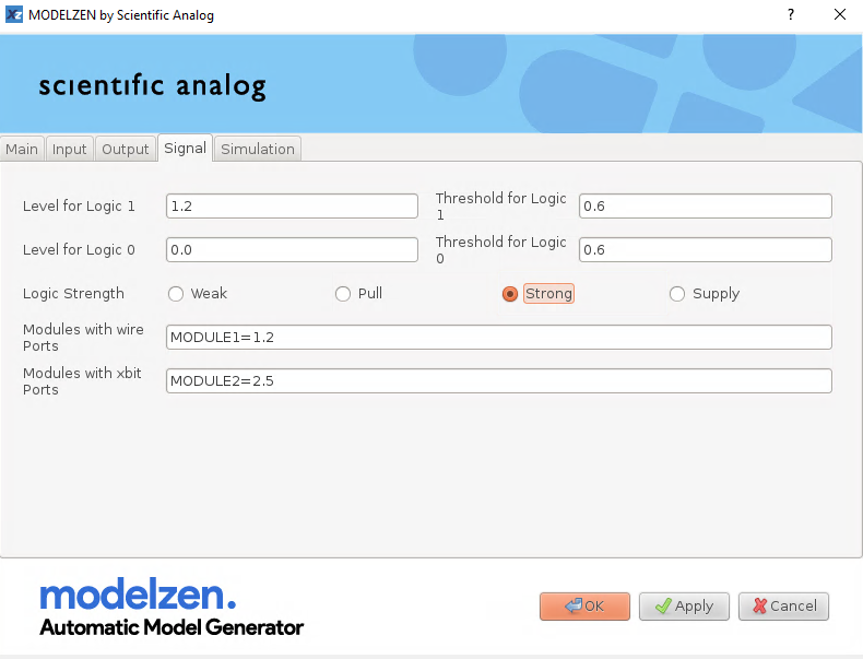
Figure 10. The MODELZEN options in the Signal tab.
Simulation Options
During the device-level characterization phase, MODELZEN performs a set of independent SPICE simulations to characterize the devices contained in the circuit netlist and map them to equivalent XMODEL primitives. When the circuit of interest has many devices with unique sets of parameter values, the number of SPICE simulations required can be large and the model generation process can take a long time. To mitigate this, MODELZEN manages a simulation directory and vault that enable recycling of the previously-run simulation results and supports running multiple SPICE simulation jobs in parallel via multi-threading.
There is a subtle difference between a simulation directory and a simulation vault. The simulation directory is where the newly- obtained simulation results are stored and recycled when they are up-to-date compared to the dependent files (e.g. no changes are made to the technology configuration file since the last run). On the other hand, the simulation vault is where the trusted simulation results are stored. In other words, the simulation results stored in the vault are always recycled regardless whether new changes are made to the dependent files. For instance, one can pre-characterize all the devices contained in the database first and move the resulting simulation directory to a new location and use it as a vault. This vault option is provided so that users can skip simulations when they know for sure that the subsequent changes made to the dependent files do not require re-simulation. However, the users must use cautions maintaining the vault up-to-date.
Table 6. Listing of options related to simulation.
| Option | Description |
--sim SIMULATOR, |
SPICE simulator to use for circuit characterization. Possible values are hspice, spectre, or finesim. |
--simdir DIRPATH |
Path of the directory storing the simulation results. If the results are up-to-date (e.g. no changes made to the technology configuration file since the last run), they will be recycled to avoid repeated simulations on the same device. The default value is ./xmodel.sim. |
--simvault DIRPATH, |
Path of the directory storing the trusted simulation results called a vault. The results stored in the vault are trusted as correct and are always recycled even when the technology configuration file is updated with changes. Cautions are required maintaining the vault. |
-t NUM_THREADS, |
Perform simulation on multiple threads. When specified with a value greater than 1, MODELZEN launches multiple SPICE simulations in parallel to generate models more quickly. However, it will consume more SPICE licenses. |
-r, --rerun, |
Force new simulation without recycling the previous results stored in the simulation directory. |
-v, --verbose |
Display verbose messages during model generation. |
--log FILENAME, |
Filename of the output log. The default value is ./modelzen.log. |
The options listed in Table 6 correspond to the ones found in the Simulation tab of the MODELZEN GUI window shown in Figure 11.
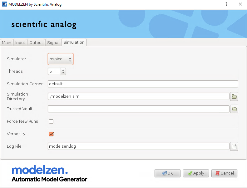
Figure 11. The MODELZEN options in the Simulation tab.