Setting Up GLISTER
The chapter explains how to set up and configure GLISTER. For more complete documentation on installing and setting up XMODEL, GLISTER, and MODELZEN, please refer to the XMODEL Installation and Setup Guide.
Configuring GLISTER on Cadence® Virtuoso®
If you’d like to use GLISTER to compose analog models in schematic forms and run XMODEL simulation within the Cadence® Virtuoso® Design Environment, you need to perform the following configuration steps.
Installing XMODEL Registry Files
GLISTER introduces new viewtypes such as xmodel and tb_xmodel as well as new environment variables and menu interfaces for the GLISTER-ADE integration. To put them into effect, you need to install the XMODEL registry files. There are multiple ways of doing this depending on whether you’re a CAD administrator or an end-user.
If you are a CAD administrator with the write permission into the Cadence® installation directory and you’d like the XMODEL registry files to be effective for all projects using a particular version of Cadence® Virtuoso®, the easiest way is to use the following command to install the XMODEL registry files directly into the Cadence® Virtuoso® installation directory:
$XMODEL_HOME/bin/setup_registry --cdshome $CDSHOME
Here, the $XMODEL_HOME is the environment variable defining the XMODEL installation path and the $CDSHOME is the environment variable defining the installation path of the Cadence® IC package. The older versions of Cadence® IC package (e.g. IC5.1) may use $CDS_INST_DIR instead of $CDSHOME.
An example of running this command is shown below. You may supply an additional --dryrun option to the registry installer script setup_registry to see what actions the script will perform before actually installing the registry files.
$ $XMODEL_HOME/bin/setup_registry --cdshome $CDSHOME
*** setup_registry (XMODEL Release 2018.03 (x86_64))
The XMODEL registry files will be installed into the following Cadence installation directory:
    /cad/cadence/IC_06.17.717

Do you want to proceed? [y/N]: y

Installing the XMODEL registry files...
cp -R /cad/scianalog/xmodel_2018.03/cadence/etc/registry/* /cad/cadence/IC_06.17.717/share/cdssetup/registry/
cp -R /cad/scianalog/xmodel_2018.03/cadence/etc/tools/* /cad/cadence/IC_06.17.717/tools/dfII/etc/tools/

XMODEL registry files are successfully installed.
As of XMODEL Release 2018.03, the registry installer script installs the following four files into the Cadence® installation directory:
$CDSHOME/share/cdssetup/registry/data/xmodel.reg$CDSHOME/share/cdssetup/registry/tools/xmodel.reg$CDSHOME/tools/dfII/etc/tools/xmodel/xmodel.cdsenv$CDSHOME/tools/dfII/etc/tools/menus/xmodel.menus
Note that these files do not interfere with any other parts of the Cadence® software or user customizations. Hence, it is safe to install these files without worrying about affecting your existing customizations.
If you don’t have the administrator privilege to modify the Cadence® installation directory, or if you want the XMODEL registry files to be effective only for a certain project or site, an alternative way is to install the XMODEL registry files into one of the local directories that can be reached by the Cadence® Setup Search File (CSF) mechanism. The local directory can be either your local work directory where you launch Cadence® Virtuoso® from, your home directory ($HOME), project directory ($CDS_PROJECT), or site directory ($CDS_SITE).
Depending on where you install the registry files, the XMODEL registry files will take effects for different range of projects and users. For instance, if you install the registry files into a local work directory, they will be effective only for the Virtuoso sessions started from that directory. On the other hand, if you install them to your home directory, they will be effective for all Virtuoso sessions started by you. If you install them into the directory pointed by $CDS_PROJECT or $CDS_SITE environment variable, they will be effective to everyone who shares the same $CDS_PROJECT or $CDS_SITE setting.
You can use the following command to install the XMODEL registry files into a local directory of your choice. Basically, change into the local directory and execute the setup_registry script with a --local option as below:
cd $CDS_PROJECT or <your cadence work directory>
$XMODEL_HOME/bin/setup_registry --local .
An example of running this command is shown below. Again, you may use an additional --dryrun option to see what actions the registry installer script will perform before actually installing the registry files.
$ cd /home/user/cadence
$ $XMODEL_HOME/bin/setup_registry --local .
*** setup_registry (XMODEL Release 2018.03 (x86_64))
The XMODEL registry files will be installed into the following local directory:
    /home/user/cadence

Do you want to proceed? [y/N]: y

Installing the XMODEL registry files...
mkdir -p /home/user/cadence/menus
cp -RL /cad/scianalog/xmodel_2018.03/cadence/etc/menus/* /home/user/cadence/menus/
cp -L /cad/scianalog/xmodel_2018.03/cadence/etc/xmodel.cdsenv /home/user/cadence/
cp /cad/scianalog/xmodel_2018.03/cadence/etc/data.reg /home/user/cadence/data.reg
cp /cad/scianalog/xmodel_2018.03/cadence/etc/csfLookupConfig /home/user/cadence/csfLookupConfig

XMODEL registry files are successfully installed.
As of XMODEL Release 2018.03, the registry installer script installs or modifies the following four files in the local directory:
xmodel.cdsenvmenus/xmodel.menusdata.regcsfLookupConfig
For more information about the CSF mechanism or the $CDS_PROJECT and $CDS_SITE directories, please refer to the Cadence® Application Infrastructure User Guide located in $CDSHOME/doc/caiuser/caiuser.pdf.
Editing .cdsinit File
The next step is to configure your Cadence® Virtuoso® environment so that the Virtuoso® Schematic Editor executes the following SKILL commands upon start-up:
; XMODEL/Virtuoso Integration Setup
XMODEL_HOME = getShellEnvVar("XMODEL_HOME")
loadContext( strcat( XMODEL_HOME "/cadence/etc/xmodel.cxt" ) )
callInitProc( "xmodel" )
For instance, you can insert these lines in the site-wide or personal .cdsinit file which is located in the $CDS_SITE directory or in the Cadence® working directory ($CDS_PROJECT), respectively. Note that the shell environment variable $XMODEL_HOME must be defined prior to launching Virtuoso®.
Editing cds.lib File
To access the libraries of the XMODEL primitive symbols and modeling examples, you need to edit your cds.lib file to include the XMODEL-related libraries. Please refer to ${XMODEL_HOME}/cadence/etc/cds.lib for the lines to be inserted in your cds.lib.
One way is to simply include this whole cds.lib file into yours by adding the following line in your local cds.lib file:
INCLUDE ${XMODEL_HOME}/cadence/etc/cds.lib
Or, you can selectively include the libraries by adding the lines individually:
DEFINE xmodel_prims   ${XMODEL_HOME}/cadence/xmodel_prims
DEFINE xmodel_blocks  ${XMODEL_HOME}/cadence/xmodel_blocks
The xmodel_prims and xmodel_blocks libraries are the minimal set of libraries required to use GLISTER.
XMODEL_SIMDIR Environment Variable (Optional)
When GLISTER performs netlisting, it stores the generated model files and other supporting files in the directory defined by the $XMODEL_SIMDIR environment variable.
In a bash-like shell, you can define this environment variable by using the following shell command:
export XMODEL_SIMDIR=$CDS_PROJECT/xmodel.sim
And in a csh-like shell, you can define it by:
setenv XMODEL_SIMDIR $CDS_PROJECT/xmodel.sim
If the $XMODEL_SIMDIR is not defined, the assumed default value is $CDS_PROJECT/xmodel.sim. If $CDS_PROJECT is not defined, then $XMODEL_SIMDIR is defaulted to $HOME/xmodel.sim.
XMODEL_LICENSE_TIMEOUT Environment Variable (Optional)
Using GLISTER features within the Cadence® Virtuoso® Design Environment checks out a GLISTER license feature. The checked-out GLISTER license does not get checked back in unless the user explicitly does so (e.g. by closing the Virtuoso session) or a specified inactivity period elapses.
You can customize this time-out period by defining the $XMODEL_LICENSE_TIMEOUT environment variable. For instance, using the following shell command in a bash-like shell defines the time-out period as 240 minutes (i.e., 4 hours):
export XMODEL_LICENSE_TIMEOUT=240
The equivalent command in a csh-like shell is:
setenv XMODEL_LICENSE_TIMEOUT 240
If you prefer setting the time-out period in the .cdsinit file, you can define a SKILL variable named xmodelLicenseTimeOut with the desired time-out period in minutes after the XMODEL/GLISTER context file is loaded:
; XMODEL/Virtuoso Integration Setup
XMODEL_HOME = getShellEnvVar("XMODEL_HOME")
loadContext( strcat( XMODEL_HOME "/cadence/etc/xmodel.cxt" ) )
callInitProc( "xmodel" )

xmodelLicenseTimeOut = 240
If neither the $XMODEL_LICENSE_TIMEOUT environment variable nor the xmodelLicenseTimeOut SKILL variable is defined, the default time-out period of 24 hours (i.e., 1440 minutes) is assumed.
Configuring GLISTER for MODELZEN
If you’d like to use MODELZEN via GLISTER interface, you may need to perform some additional configuration steps:
- Override the MODELZEN-related GLISTER default options if necessary
- Configure how MODELZEN extracts circuit netlists from schematic cellviews (
modelzenGenNetlist())
Overriding MODELZEN-related GLISTER Default Options
GLISTER provides some MODELZEN-related options that control the ways GLISTER executes MODELZEN within the Cadence® Virtuoso® Design Environment. These options can be modified from the Set MODELZEN Options dialog box that opens when selecting the GLISTER->Set MODELZEN Options menu from the Cadence® Virtuoso® Schematic Editor window.
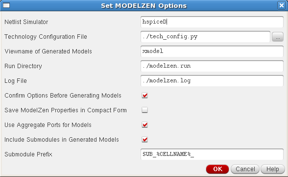
Figure 1. The dialog box for setting MODELZEN options.
For instance, the Netlist Simulator field sets the format of the circuit netlist to be extracted from the schematic cellview and the Technology Configuration File field sets the default technology configuration file to be used by MODELZEN. Please refer to the MODELZEN User’s Guide for more detailed descriptions on each of these options.
One can override the default values of the MODELZEN-related GLISTER options by overriding the values of the SKILL variables that correspond to these options after loading the XMODEL/GLISTER context file. An excerpt of the Cadence® Virtuoso® initialization file .cdsinit that overrides some of the MODELZEN-related GLISTER options is listed below. The first part initializes the GLISTER interface for Cadence® Virtuoso® as previously explained in Section 2.1. The second part redefines some SKILL variables with a prefix modelzen to override the default values of the MODELZEN-related GLISTER options.
; XMODEL/Virtuoso Integration Setup
printf( "Loading XMODEL/Virtuoso Integration...\n" )
XMODEL_HOME = getShellEnvVar("XMODEL_HOME")
loadContext( strcat( XMODEL_HOME "/cadence/etc/xmodel.cxt" ) )
callInitProc( "xmodel" )

; MODELZEN options (NOTE: must come after context file loading)
modelzenDefaultModelView = "xmodel"
modelzenDefaultConfigFile = "./tech_config.py"
modelzenDefaultRunDir = "./modelzen.run"
modelzenDefaultNetlistSimulator = "hspiceD"
modelzenSubModulePrefix = "SUB_%CELLNAME%_"
modelzenShowOptionDialog = t
Table 1 lists the names of the SKILL variables that define the default values of the MODELZEN-related GLISTER options shown in Figure 1.
Table 1. Listing of the SKILL variables setting the default values of the MODELZEN-related GLISTER options.
| Option Name | Corresponding SKILL Variable Name |
| Netlist Simulator | modelzenDefaultNetlistSimulator |
| Technology Configuration File | modelzenDefaultConfigFile |
| Viewname of Generated Models | modelzenDefaultModelView |
| Run Directory | modelzenDefaultRunDir |
| Log File | modelzenDefaultLogFile |
| Confirm Options Before Generating Models | Set modelzenShowOptionDialog as t to select this flag |
| Save MODELZEN Properties in Compact Form | Set modelzenIncludeAllPinInfo as nil to select this flag |
| Use Aggregate Ports for Models | Set modelzenUseAggregatePorts as t to select this flag |
| Include Submodules in Generated Models | Set modelzenSubModulePrefix with any string to select this flag; setting it as nil unselects this flag |
| Submodule Prefix | modelzenSubModulePrefix |
Configure How MODELZEN Extracts Circuit Netlists from Schematic Cellviews
Running MODELZEN using the GLISTER interface involves extracting a circuit netlist from the schematic cellview. If your design environment uses a customized procedure or interface for extracting SPICE or Spectre netlists from the schematic cellview, you may need to redefine a SKILL procedure named modelzenGenNetlist() in order for MODELZEN to use the same steps when extracting the circuit netlists.
The usage format of the SKILL function modelzenGenNetlist() is shown as below:
modelzenGenNetlist( libName cellName viewName simulator )
The function takes four arguments libName, cellName, viewName, and simulator where libName, cellName, and viewName are the library, cell, and view names of the design cellview to be netlisted, respectively, and simulator is the name of the Cadence® netlist simulator that determines the format of the netlist (e.g. hspiceD, spectre, and cdl). The function then extracts a netlist from the cellview and returns the full path to the extracted netlist file.
To redefine the modelzenGenNetlist() function, one may need to know the basics of SKILL programming and specific steps required for netlisting in her or his design environment. Please refer to the appropriate Cadence® documentations, or consult your PDK providers or CAD administrators in case you need further help.
The following codes show the default modelzenGenNetlist() function which is defined when the XMODEL/GLISTER context file is first loaded. It extracts the netlist using the Cadence® Analog Design Environment (ADE) SKILL functions such as simulator(), design(), and createNetlist(). If you can extract netlists from your schematic cellview using the standard ADE interface, it is likely that you do not need to redefine modelzenGenNetlist().
; modelzenGenNetlist( libName cellName viewName simulator ):
; generates the 'simulator' netlist of a cellview and
; returns the full filepath of the generated netlist
procedure( modelzenGenNetlist( libName cellName viewName simulator )
    let( ( netlistFile netlistDir )
        ; initialize simulator
        simulator( simulator )

        ; generate netlist
        design( libName cellName viewName )
        unless( netlistFile = createNetlist( ?recreateAll t ?display nil )
            error( "error occurred while netlisting %s.%s:%s."
                    libName cellName viewName )
        )
        ocnCloseSession()

        ; return netlist filename
        netlistDir = xmodelGetDirName( netlistFile )
        strcat( netlistDir "/netlist" )
    )
)
Testing with Examples
You can try the following steps to check whether the configuration of GLISTER has been done successfully. Namely, you can try browsing the schematics for a charge-pump phase-locked loop (PLL) model made of XMODEL primitives, netlisting the schematics into SystemVerilog models, and running the XMODEL simulation and viewing the waveforms directly from the Cadence® Virtuoso® Design Environment.
Add the Example Library
As a first step, add the provided library named example to your Cadence® Virtuoso® Design Environment by adding the following line to your cds.lib file:
DEFINE example ${XMODEL_HOME}/cadence/example
Note that this step is not necessary if you have already included the whole ${XMODEL_HOME}/cadence/etc/cds.lib into your cds.lib file as below:
INCLUDE ${XMODEL_HOME}/cadence/etc/cds.lib
Open the Model Schematic of a Charge-Pump PLL
Now, start the Virtuoso session and open a cellview named example:tb_cp_pll:schematic. In other words, open a cellview with a library name example, cell name tb_cp_pll, and view name schematic. One way of opening a cellview from Cadence® Virtuoso® is to open the Library Manager window by selecting the Tools->Library Manager menu from the Command Interpreter Window (CIW) and select the corresponding library, cell, and view from the Library Manger window in sequence. Please refer to the Cadence® documentations for further details.
When you succeed, you will get a top-level schematic for the charge-pump PLL and its testbench as shown in Figure 2. Try browsing its design hierarchies to see how a charge-pump PLL can be modeled using XMODEL primitives.
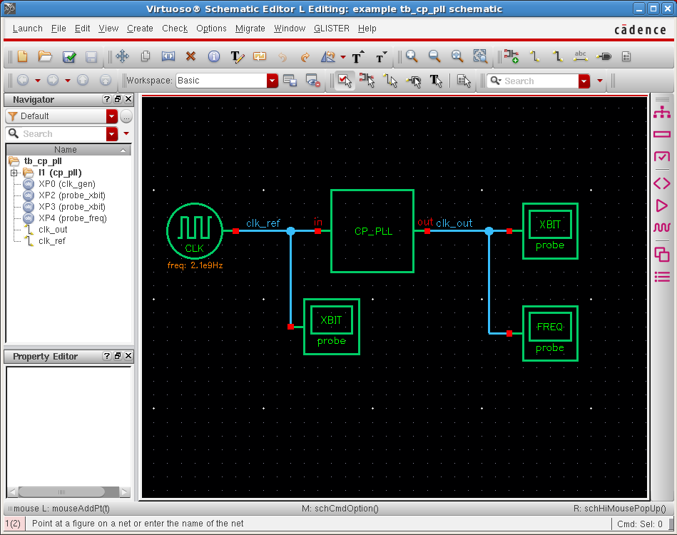
Figure 2. Schematic of a cellview example:tb_cp_pll:schematic.
Generate XMODEL Netlist from Schematic
As a next step, let’s try to netlist models from this schematic representation of the PLL. The GLISTER actions are available both from the pull-down menu and from the toolbar menu of the schematic editor as shown in Figure 3. To generate XMODEL netlists from the currently-editing schematic, select the GLISTER->Generate XMODEL Netlist pull-down menu or press the  icon from the toolbar menu.
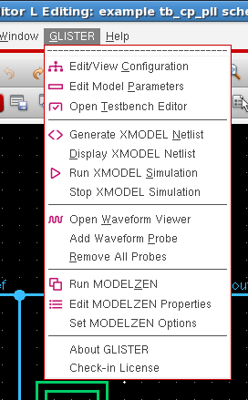
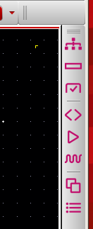
Figure 3. The GLISTER pull-down menu (left) and toolbar menu (right).
To view the model netlists generated, select the GLISTER->Display XMODEL Netlist pull-down menu. Then, a text-editor window will pop-up and show the contents of the model netlists generated as in Figure 4. Note that this example charge-pump PLL model consists of multiple source files, each of which is displayed on a separate tab of the text-editor window.
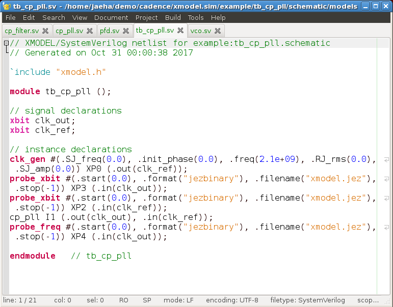
Figure 4. Text-editor window displaying the generated netlist models.
Launch XMODEL Simulation
You can also run XMODEL simulations using the generated testbench and model files simply by selecting the GLISTER->Run XMODEL Simulation pull-down menu or clicking the  icon from the toolbar. Note that the XMODEL simulator and SystemVerilog simulator of your choice must be configured properly for your environment prior to performing this action. For further information, please refer to the XMODEL Installation and Setup Guide.
When you run the XMODEL simulations from the GLISTER environment, the output logs of the simulation will be displayed inside the Command Interpreter Window (CIW), as shown in Figure 5.
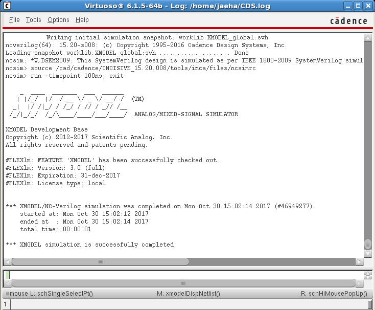
Figure 5. The Command Interpreter Window (CIW) displaying the output logs of the XMODEL simulation.
View Waveforms with XWAVE
You can view the resulting waveforms of the simulation by selecting the GLISTER->Open Waveform Viewer pull-down menu or clicking the  icon on the toolbar. Once the XWAVE Waveform Viewer window pops-up, select the signals of which waveforms you want to view. Figure 6 is a screenshot of the XWAVE Waveform viewer displaying the waveforms of the reference clock, output clock, and output frequency of the phase-locked loop going through an initial locking transient.
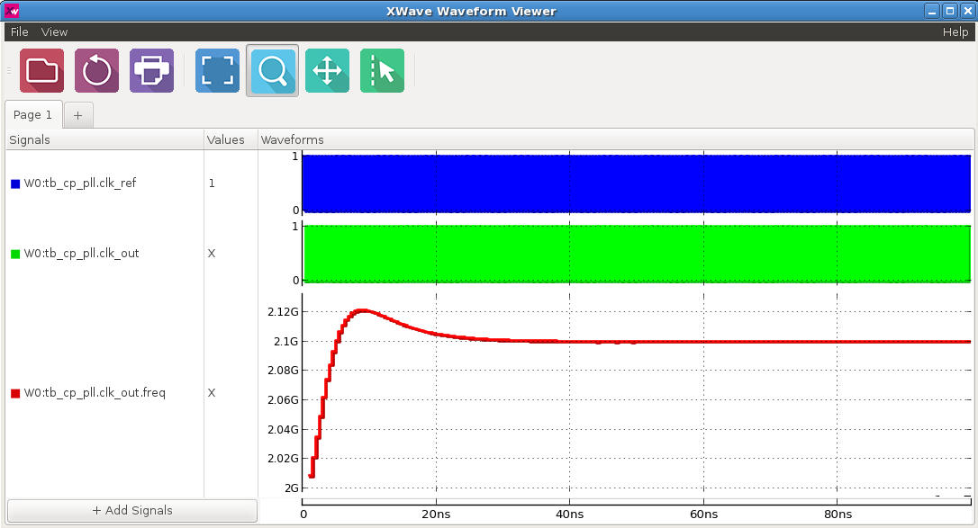
Figure 6. XWAVE Waveform Viewer displaying the simulated waveforms of the charge-pump PLL.